Systems and methods for adjusting a display based on the user's position

a technology of display and user position, applied in the field of system and method for adjusting a display based on the user's position, can solve the problems of hardly intuitive, may even be frustrating for new users, and the objects displayed on the electronic device screen may lack realism, so as to achieve accurate assessment of the user's position

Active Publication Date: 2009-12-17
APPLE INC
View PDF20 Cites 338 Cited by
  • Summary
  • Abstract
  • Description
  • Claims
  • Application Information

AI Technical Summary

Benefits of technology

[0004]An electronic device operative to change the perspective of displayed three-dimensional objects based on the user's position relative to the electronic device is provided. The electronic device may include a display for displaying objects, and a sensing mechanism for detecting the user's position. The sensing mechanism may be operative to detect the user's position using any suitable sensing approach, including for example optically (e.g., using a camera or lens), from emitted invisible radiation (e.g., using an IR or UV sensitive apparatus), electromagnetic fields, or any other suitable approach. The sensing mechanism may be placed in any suitable position relative to the display. For example, the sensing mechanism may be integrated in or adjacent the display (e.g., as an integrated camera above the display). This may allow the sensing mechanism a more accurate assessment of the user's position relative to the display. For example, if the sensing mechanism is integrated with the display, the sensing mechanism may detect the user's head using a camera, and determine the position of the user's head relative to the center of the display.
[0007]To make the displayed objects more realistic to the user, the electronic device may detect the user's environment and map the detected environment to the displayed objects. For example, using a camera, the electronic device may capture images of the user and of the user's environment. The electronic device may then simultaneously modify the object displayed based on the user's perspective and map the images of the captured environment to the displayed object. For example, the electronic device may define visual properties of different surfaces of the displayed object (e.g., reflection and refraction characteristics), and apply the visual properties to the portions of the detected image mapped on each surface. Using this approach, surfaces with low reflectivity (e.g., plastic surfaces) may not reflect the environment, but may reflect light, while surfaces with high reflectivity (e.g., polished metal or chrome) may reflect both the environment (e.g., the user's face as detected by the camera) and light. To further enhance the user's experience, the detected environment may be reflected differently along curved surfaces of a displayed object (e.g., as if the user were actually moving around the displayed object and seeing his reflection based on his position and the portion of the object reflecting the image).

Problems solved by technology

While this approach for viewing three-dimensional objects may be functional, it is hardly intuitive and may even be frustrating for new users, as they discover and learn the input device sequences used for each manipulation of the object.
Furthermore, objects displayed on the electronic device screen may lack realism, because the electronic device cannot know the user's environment from which the object is being viewed.

Method used


Image

  • Systems and methods for adjusting a display based on the user's position
  • Systems and methods for adjusting a display based on the user's position
  • Systems and methods for adjusting a display based on the user's position

Examples


Embodiment Construction

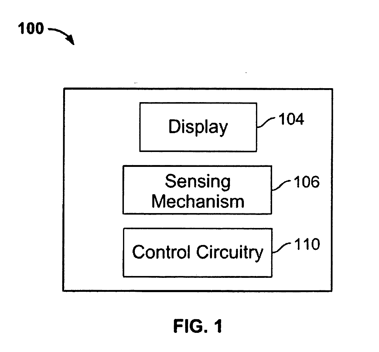
[0033]FIG. 1 is a schematic view of a electronic device in accordance with one embodiment of the invention. Electronic device 100 may include display 104, sensing mechanism 106, and control circuitry 110. In some embodiments, electronic device 100 may include other components, including for example, an input mechanism, an audio output component, communications circuitry, a power supply, ports or interfaces for coupling to a host device, a secondary input mechanism (e.g., an ON / OFF switch), or any other suitable component.

[0034]Electronic device 102 may include any suitable device operative to display information to a user. For example, electronic device 102 may include a media player such as an iPod available by Apple Inc., of Cupertino, Calif., a cellular telephone, a personal e-mail or messaging device (e.g., a Blackberry® or a Sidekick®), an iPhone available from Apple Inc., pocket-sized personal computers such as an iPAQ Pocket PC available by Hewlett Packard Inc., of Palo Alto,...


PUM


Abstract

An electronic device for providing a display that changes based on the user's perspective is provided. The electronic device may include a sensing mechanism operative to detect the user's position relative a display of the electronic device. For example, the electronic device may include a camera operative to detect the position of the user's head. Using the detected position, the electronic device may be operative to transform displayed objects such that the displayed perspective reflects the detected position of the user. The electronic device may use any suitable approach for modifying a displayed object, including for example a parallax transform or a perspective transform. In some embodiments, the electronic device may overlay the environment detected by the sensing mechanism (e.g., by a camera) to provide a more realistic experience for the user (e.g., display a reflection of the image detected by the camera on reflective surfaces of a displayed object).

Description

BACKGROUND OF THE INVENTION [0001]Using electronic devices, a user may view images of real or artificial three-dimensional objects. For example, a user surfing the Internet can view images of products available for purchase. As another example, a user of a graphic application (e.g., a CAD application) may create three-dimensional objects.[0002]To view different perspectives of the three-dimensional objects, existing electronic devices may require the user to perform manipulations using input mechanisms, such as arrow keys or letter keys on a keyboard, mouse clicks and mouse movements, or combinations of inputs using different input mechanisms. For example, the user may provide a particular input device sequence to cause a displayed object to pan or rotate.[0003]While this approach for viewing three-dimensional objects may be functional, it is hardly intuitive and may even be frustrating for new users, as they discover and learn the input device sequences used for each manipulation o...

Claims


Application Information

Patent Timeline
Patent Type & Authority Applications(United States)
IPC IPC(8): G06F3/00
CPCG06F3/012G06F3/0304G06F3/04815G09G2354/00G09G3/003G09G5/14G09G2340/04G06F2200/1637
Inventor KERR, DUNCAN R.KING, NICHOLAS V.
Owner APPLE INC
Why Eureka
Try Eureka