

Irrigation pipe
- Summary
- Abstract
- Description
- Claims
- Application Information
AI Technical Summary
Benefits of technology
Problems solved by technology
Method used
Image

Examples
Embodiment Construction
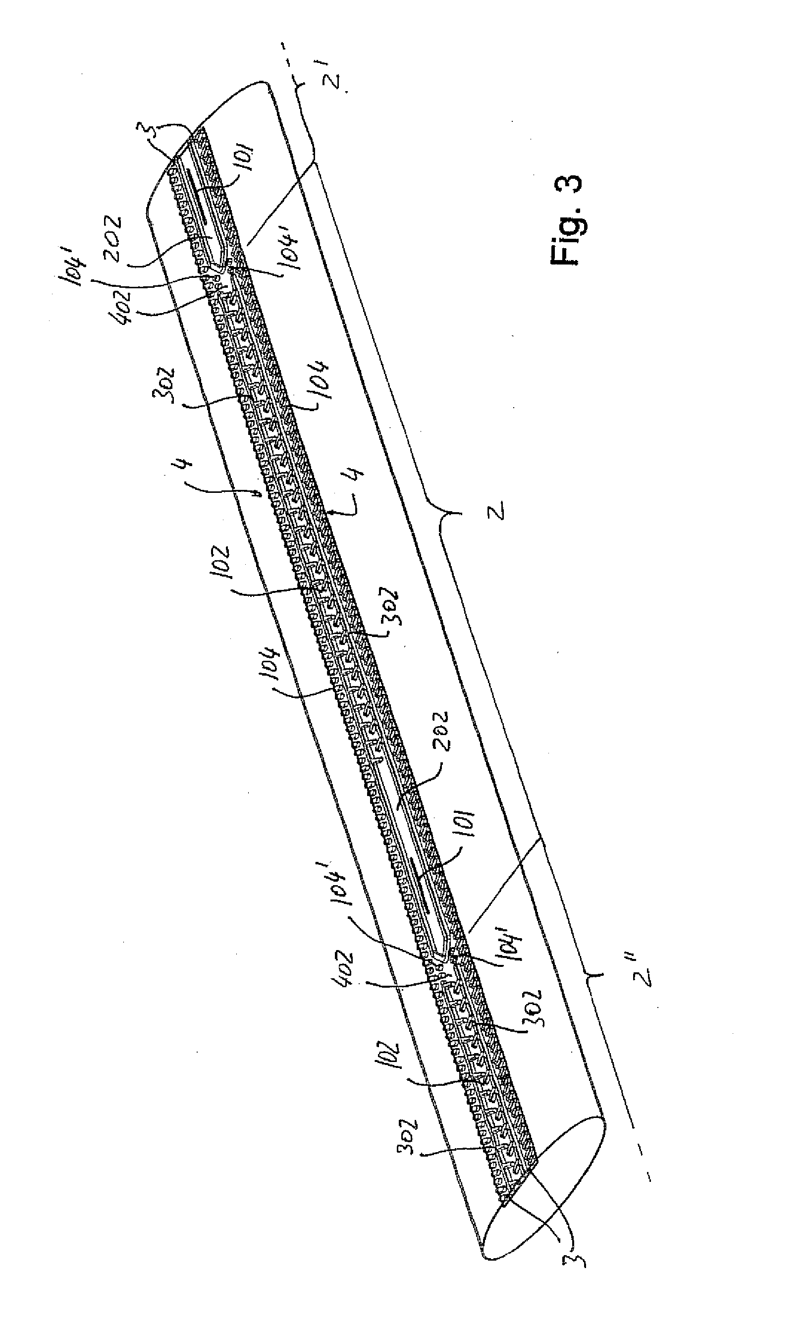
[0053]With reference to the description and claims, the term longitudinal row means a row of elements arranged one after the other along a straight line or a line oriented longitudinally in relation to the pipe, that is, preferably but not necessarily parallel to the axis of said pipe. Even if from the manufacturing point of view it is definitely faster and simpler to make the row of dripping units having an orientation according to an axis parallel to the axis of the pipe, it is not to be excluded for said row of dripping units to be extended also along an axis having a path along a not straight line for example a undulating line or an helicoidal line.
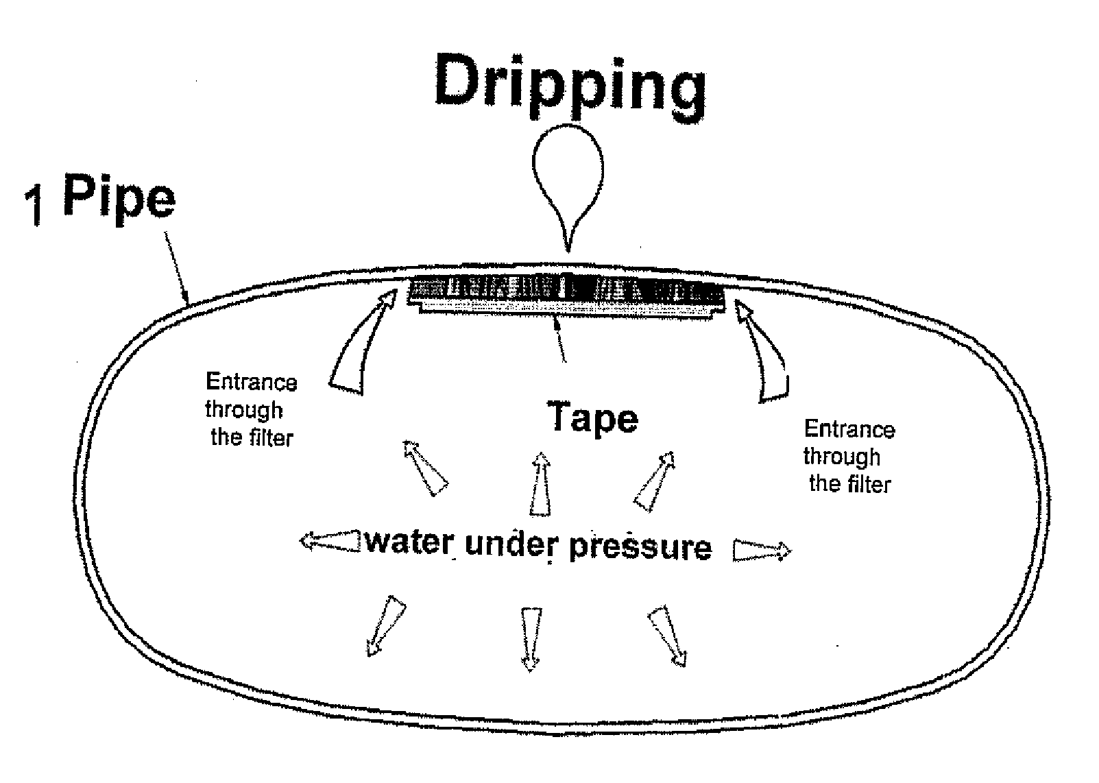
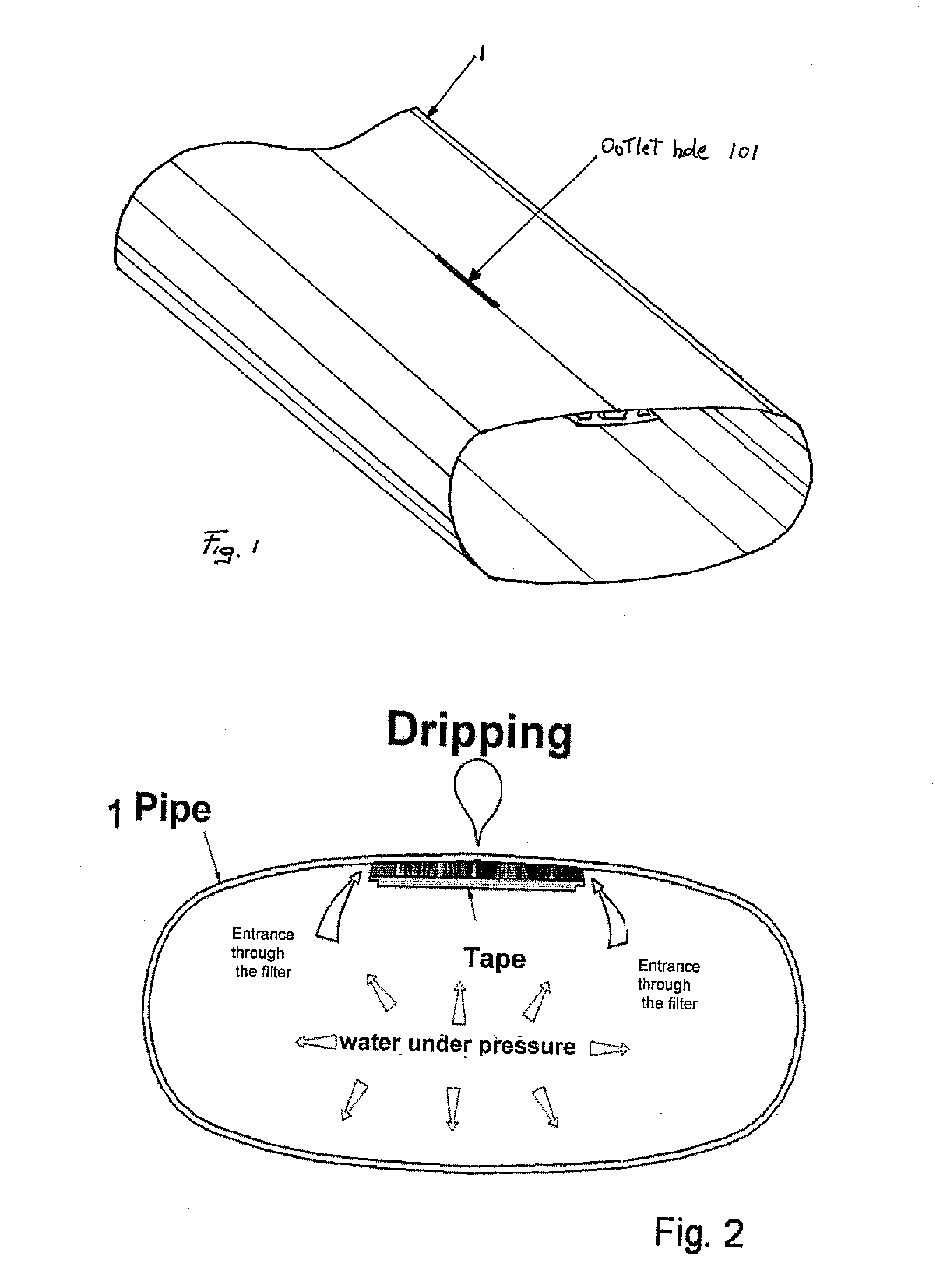
[0054]With reference to FIGS. 1 to 5, there is shown an irrigation pipe of the so called drip type. A pipe 1 having a perimetral wall completely closed in itself without interruption has a sequence of dripping units 2 inside it and along a longitudinal band of said pipe wall. Dripping units are composed of a pressure reduction element...
PUM
 Abstract
Description
Claims
Application Information