Heat exchanger

Inactive Publication Date: 2009-12-24
HALLA CLIMATE CONTROL
View PDF12 Cites 27 Cited by
  • Summary
  • Abstract
  • Description
  • Claims
  • Application Information

AI Technical Summary

Benefits of technology

[0012]According to the present invention, since a turbulent flow is generated early even when a flow rate condition of the heat exchange medium in the heat exchanger tube is unfavorable, it is possible to increase the heat exchange performance and also optimize the heat ex

Problems solved by technology

Therefore, if leaving the vehicle engine 1 as it is, it will be overheated and a metallic material used in constructing the engine 1 is melted and thus a cylinder, a piston and the like may be damaged seriously.
However, in case that the heat exchanger is installed in the vehicle, it is difficult to change a basic structure of the heat exchanger, like a size or a position of an inlet/outlet port for a heat exchange medium due to p

Method used


Image

  • Heat exchanger
  • Heat exchanger
  • Heat exchanger

Examples


Embodiment Construction

[0021]

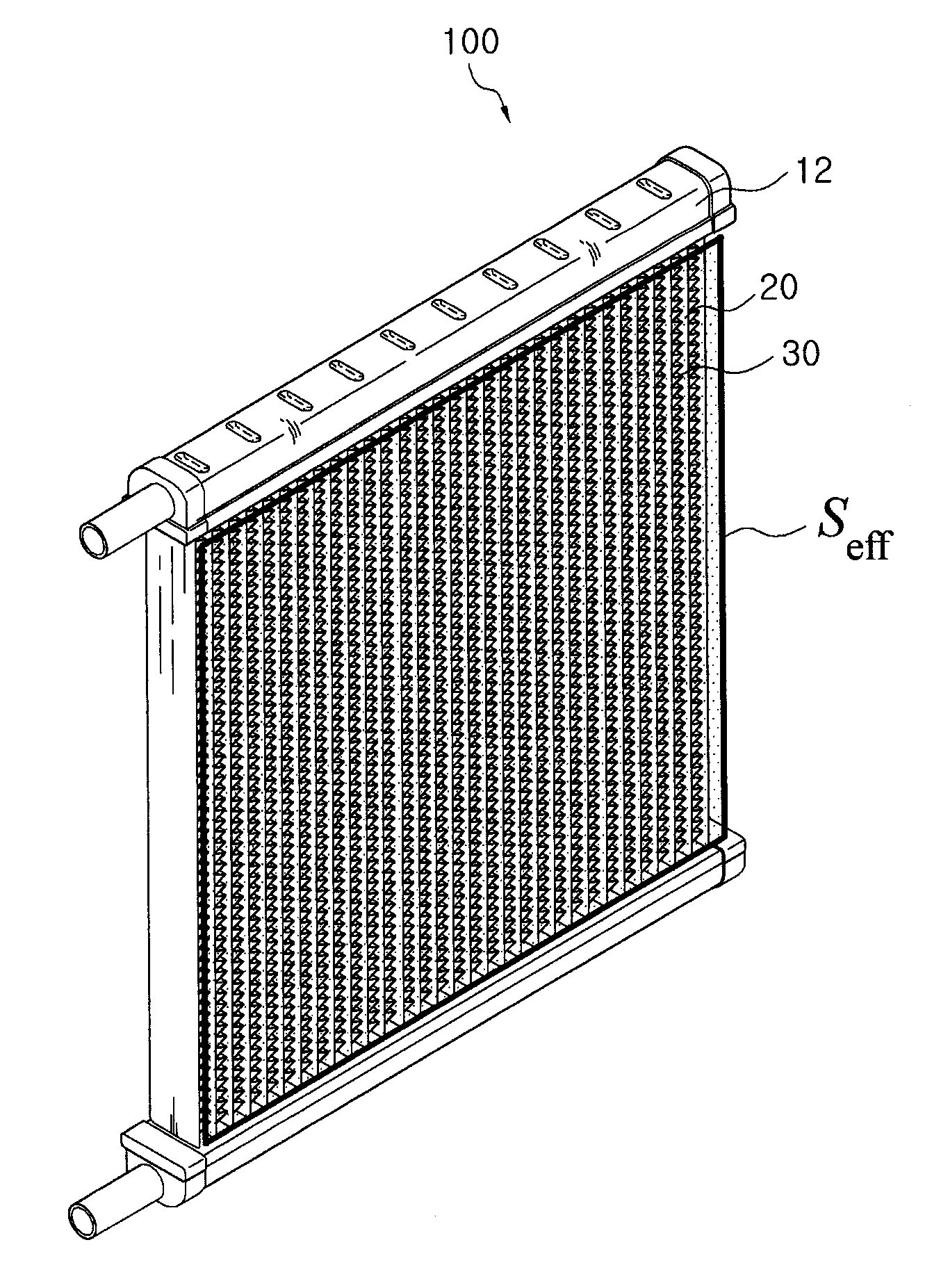
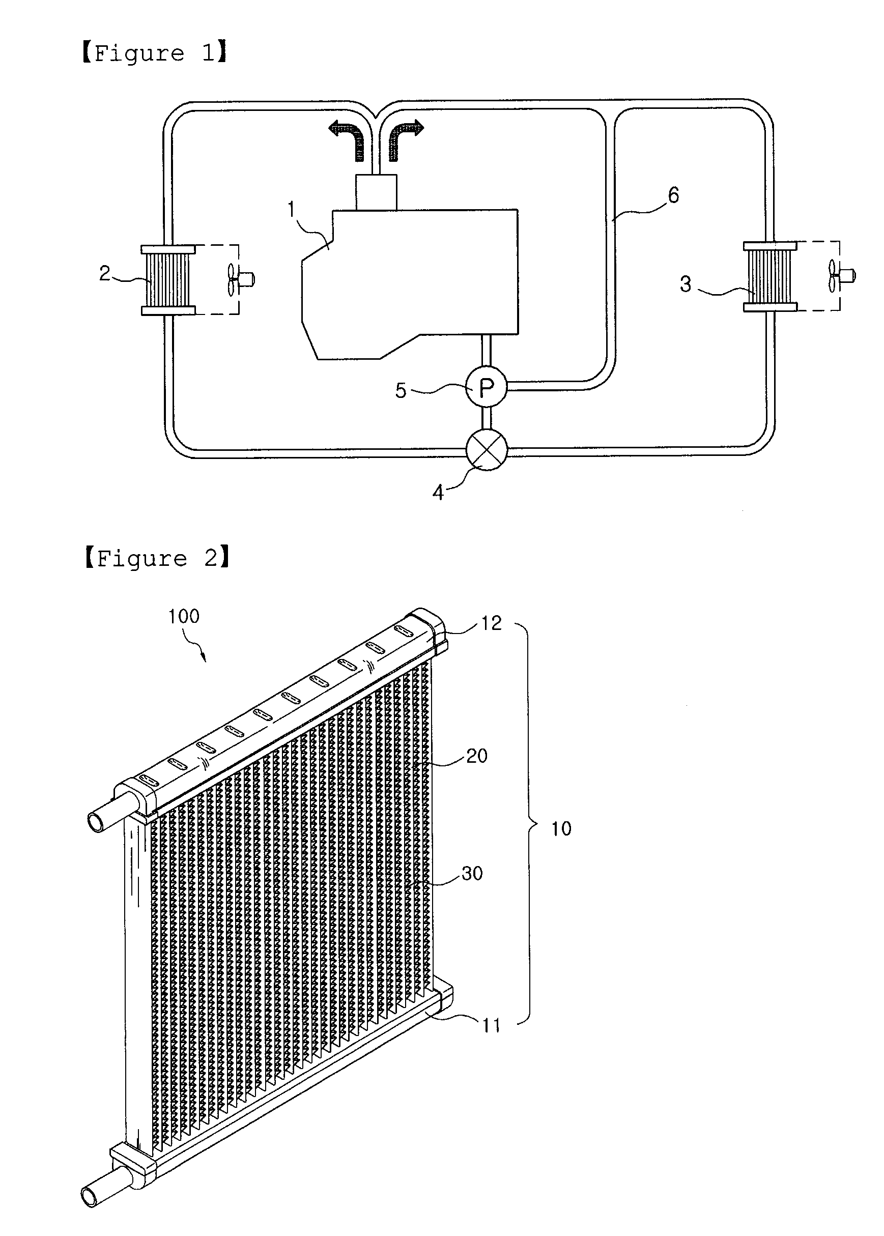
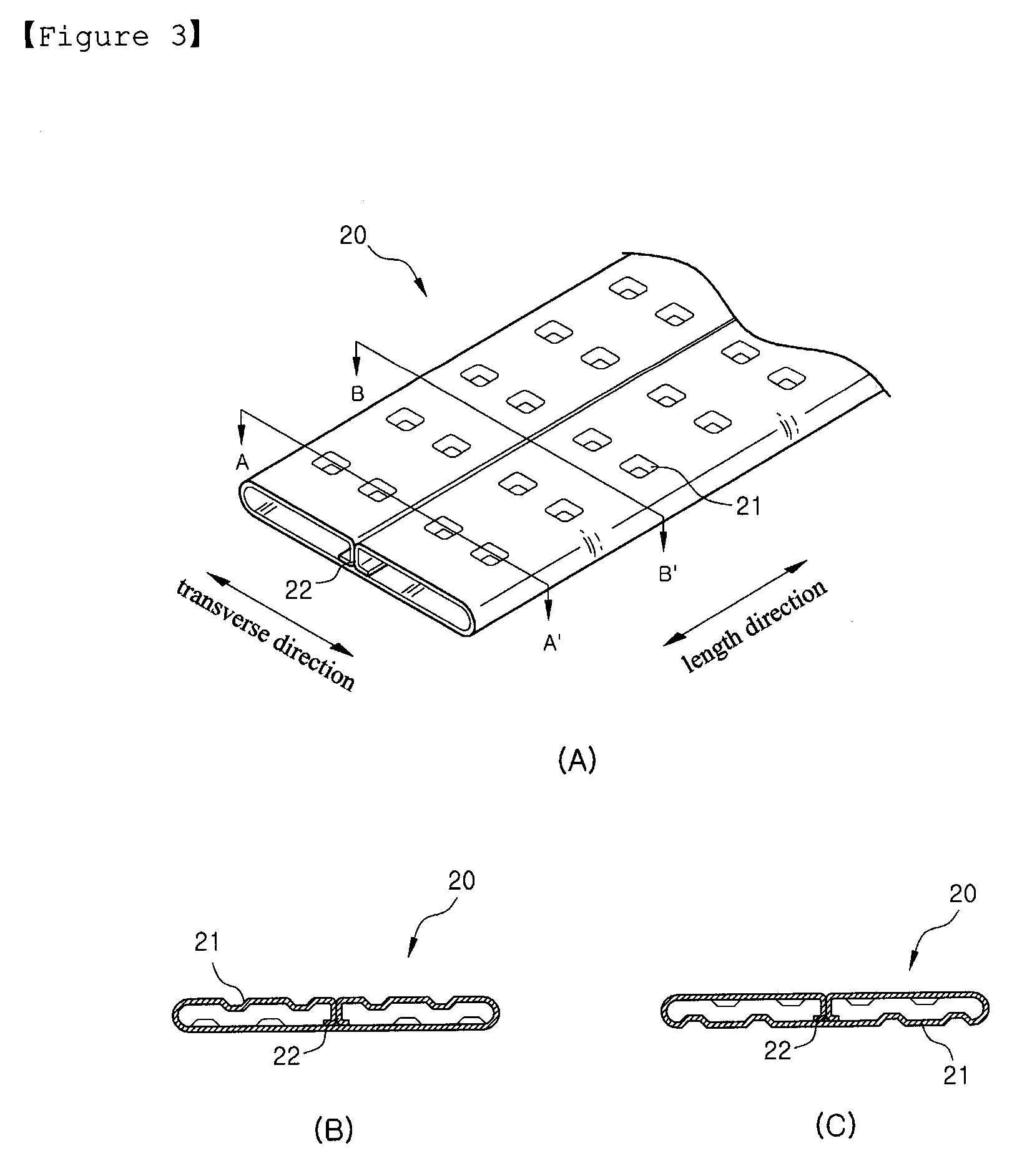
100:heat exchanger10:tank11:inlet tank12:outlet tank20:tube30:fin21:dimple22:partition wall

Best Mode

[0022]Hereinafter, the embodiments of the present invention will be described in detail with reference to accompanying drawings.

[0023]FIG. 2 is a perspective view of a heat exchanger 100. A heat exchange medium is flown in the heat exchanger 100, and the heat exchanger 100 includes a plurality of tubes 20 which are arranged in parallel at regular distances to be parallel with a ventilation direction, and tanks 10 which are respectively coupled to both ends of the tubes 20. The tanks 10 are divided into an inlet tank 11 in which the heat exchange medium is introduced and then distributed to the plurality of tubes 20 and an outlet tank 12 in which the heat exchange medium moved through the tubes 20 is collected and then discharged. Fins 30 are provided between the tubes 20 so as to increase a contact surface area with air flowing between the tubes 20. As described above, the heat ...


PUM


Abstract

A heat exchanger has plural tubes, an inlet tank, a fin, and an outlet tank. Each tube has a dimple structure for inducing a turbulent flow of heat exchange fluid flowing through each tube, thereby increasing heat exchange performance. The dimples of each tube satisfy the following formula:
8.80<thesumAdimpleoftheproductofawidthdandadepthhofeachdimplealengthLofthetube×aheightHofthetube×100<13.60

Description

TECHNICAL FIELD[0001]The present invention relates to a heat exchanger, more particularly, to a heat exchanger with a tube having a dimple structure by which a turbulent flow is generated in the tube, thereby increasing a heat exchanging performance.BACKGROUND ART[0002]FIG. 1 is a view showing a general cooling and heating system of a vehicle. In a vehicle engine 1, high temperature and high pressure gas is ignited and burned. Therefore, if leaving the vehicle engine 1 as it is, it will be overheated and a metallic material used in constructing the engine 1 is melted and thus a cylinder, a piston and the like may be damaged seriously. To prevent such damage, as shown in FIG. 1, a water jacket (not shown) in which cooling water is stored is formed around the cylinder of the vehicle engine 1 and the cooling water is circulated through a radiator 2 or a heater core 3 by a water pump 5 so as to cool the engine 1. The cooling water may be not passed through the heater core 3, but directl...

Claims


Application Information

Patent Timeline
IPC IPC(8): F28F13/12
CPCF28D1/0391F28D1/05366F28F3/044F28F1/426F28F1/42F28F1/10F28F1/00F28F9/00
Inventor JEON, YOUNG-HAKIM, KI-HONGLEE, JUNG-JAE
Owner HALLA CLIMATE CONTROL
Why Eureka
Try Eureka