
Apparatus for producing and/or processing panels

Active Publication Date: 2009-12-24
INTERGLARION LTD (AT)
View PDF26 Cites 6 Cited by
  • Summary
  • Abstract
  • Description
  • Claims
  • Application Information

AI Technical Summary

Benefits of technology

[0013]In view of this background, the present invention provides a device of the type mentioned at the outset, which transports panels, in particular also narrower panels, reliably and with high position accuracy along the transport path and which can be used with higher cost-effectiveness.

Problems solved by technology

However, in practical use it has been shown with the two known chain conveyors that in particular with the transport of narrower panels or at higher transport speeds, marked deviations from the desired position of the panels occur, which ultimately leads to a faulty processing of the panels in the processing devices or even to a breakdown of the transport and a downtime of the device associated therewith.
Furthermore, chain conveyors are structured in a relatively complex manner and, due to high frictional forces between the guide parts and the guide rails, require a relatively high energy expenditure for the drive and high maintenance and repair costs due to wear.
Although the position accuracy of the panels can be increased with the aid of the belt conveyors in particular at higher speeds, conveyors of this type are associated with high acquisition costs, since the guide rails have to be produced in an extrusion process with high precision along their entire length and may not show any deformation at all in particular with local or temporal temperature fluctuations.
The guide rails produced for this reason with relatively high material strength are not only expensive and very heavy and cumbersome due to their length and width, they are also unsuitable for transporting narrower panels, since a certain minimum distance is preset between the belts guided parallel due to the width of the rails.
Furthermore, due to the given friction between the belts and the guide rails, a relatively high drive power is necessary for the movement of the belts and a wear of these components is inevitable with longer operation, so that, in addition, the operating costs of the known device are also relatively high.
Although it has already been suggested for the known belt conveyors to reduce the friction force between the belts and the guide rails by guiding the belts on an air cushion generated in the guide groove of the guide rails, the provision of corresponding compressed-air devices leads to a further increase in the acquisition and operating costs of the device.
If a guide groove of this type is inserted in the underside of a panel, furthermore the counteracting paper applied to the underside of the panel must be cut through, which then to a large extent loses its effect for stabilizing the planar plate form of the panel so that a dishing of the panel occurs due to the tension of the laminate applied to the top of the panel.

Method used


Image

  • Apparatus for producing and/or processing panels
  • Apparatus for producing and/or processing panels
  • Apparatus for producing and/or processing panels

Examples


Embodiment Construction

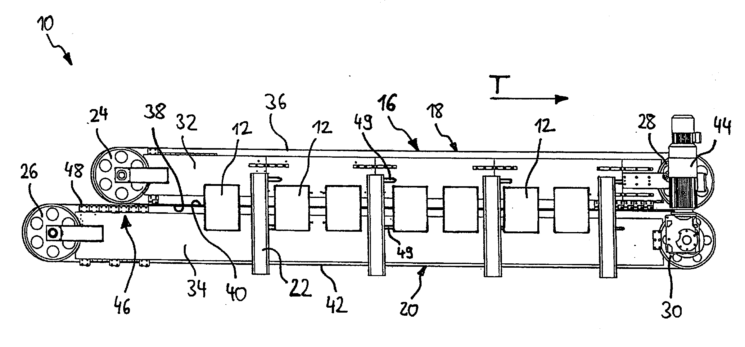
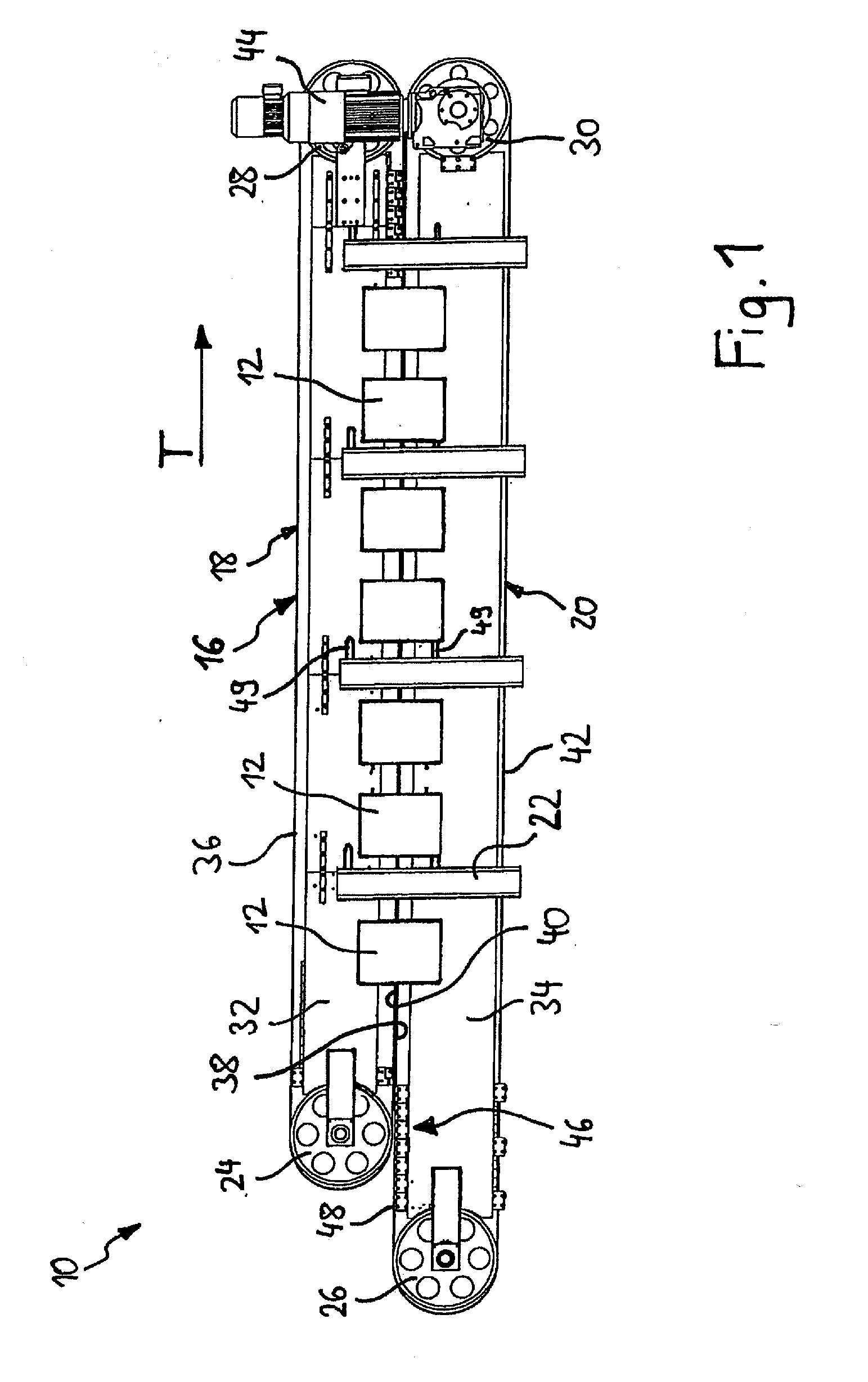
[0046]In FIG. 1 a device according to the invention for producing and / or processing panels is labeled in general by 10, in which panels to be produced or processed are transported in a transport direction T by a transport device to be described in more detail and in this manner are conveyed successively to several processing stations 12, which are shown only symbolically in FIG. 1. The processing stations 12 can be, for example, milling tools, which form a groove or a tongue on longitudinal or transverse sides of the panels, but they can also be positioning devices which perform a precise positioning of the panels necessary for the following processing station.

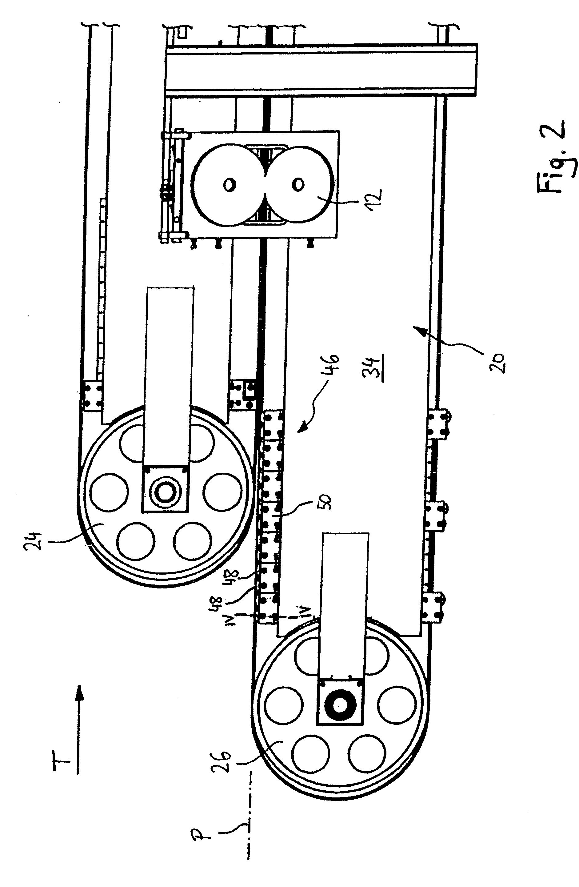
[0047]In order to convey the panels to the individual processing stations 12, a transport device of the device 10 has two double-belt conveyors 14, 16 running parallel to one another and arranged next to one another (see FIG. 3). As illustrated in FIG. 1, only the right side double-belt conveyor 16, when viewed in the transpor...


PUM


Abstract

The present invention provides a device (10) for producing and / or processing panels, comprising a transport device for transporting panels along a transport path and a processing device (12) for processing the panels during their movement by the transport device, wherein the transport device comprises two double-belt conveyor means (14, 16) with respectively one upper endless belt (36) and one lower endless belt (42), which respectively have a transport strand side (38, 40) essentially parallel to the transport path and are deflected respectively by deflection devices (24, 26, 28, 30) on the two ends of the transport strand side (38, 40), wherein the upper endless belts (36) touch a panel to be transported on the upper surface side thereof and the lower endless belts (42) touch the panel on the lower surface side thereof, and wherein at least one of the endless belts (36, 42) is guided on its transport strand side (38, 40) by means of a plurality of guide rollers (48) arranged between the deflection devices (24, 26, 28, 30).

Description

CROSS-REFERENCE TO RELATED APPLICATIONS[0001]The present application is a U.S. National Stage of International Patent Application No. PCT / EP2007 / 006731 filed Jul. 30, 2007, and claims priority of German Patent Application No. 10 2006 035 647.0 filed Jul. 31, 2006. Moreover, the disclosure of International Patent Application No. PCT / EP2007 / 006731 is expressly incorporated by reference herein in its entirety.BACKGROUND OF THE INVENTION[0002]1. Field of the Invention[0003]The present invention relates to a device for producing and / or processing panels that includes a transport device for transporting panels along a transport path and a processing device for processing the panels during their movement by the transport device.[0004]2. Discussion of Background Information[0005]Devices of this type are known, for example, in the field of the production of flooring panels for processing the longitudinal and / or transverse sides of the panels. In a known use, a milling tool is used as a proce...

Claims


Application Information

Patent Timeline
IPC IPC(8): B65G15/14
CPCB27F1/06B27M1/08B65G2201/022B65G15/60B65G15/14
Inventor KRALLINGER, RUPERT
Owner INTERGLARION LTD (AT)
Learn More