Debris capture and removal for laser micromachining

Inactive Publication Date: 2009-12-24
ELECTRO SCI IND INC
View PDF2 Cites 45 Cited by
  • Summary
  • Abstract
  • Description
  • Claims
  • Application Information

AI Technical Summary

Benefits of technology

[0009]The disclosed system contains ejected surface debris and thereby enables automatic capture and disposal of the surface debris and the axial debris produced by the laser micromachining of the target specimen. The flexible fiber brush material sustains temperatures of up to at leas

Problems solved by technology

Machining metals and other target specimens using a laser beam generates a significant amount of molten debris.
Without proper debris containment during the laser micromachining process, the laser system becomes polluted with axial debris and requires daily cleaning and maintenance.
In addition, surface debris may block the laser beam cutting path, reducing ablation efficiency.
Most laser micromachining systems are designed with proper covers and shields to protect sensitive subsystem components from vapor and molten deposits, but these shields intercept and trap only a small portion of the ejected material.
Although they protec

Method used


Image

  • Debris capture and removal for laser micromachining
  • Debris capture and removal for laser micromachining
  • Debris capture and removal for laser micromachining

Examples


Embodiment Construction

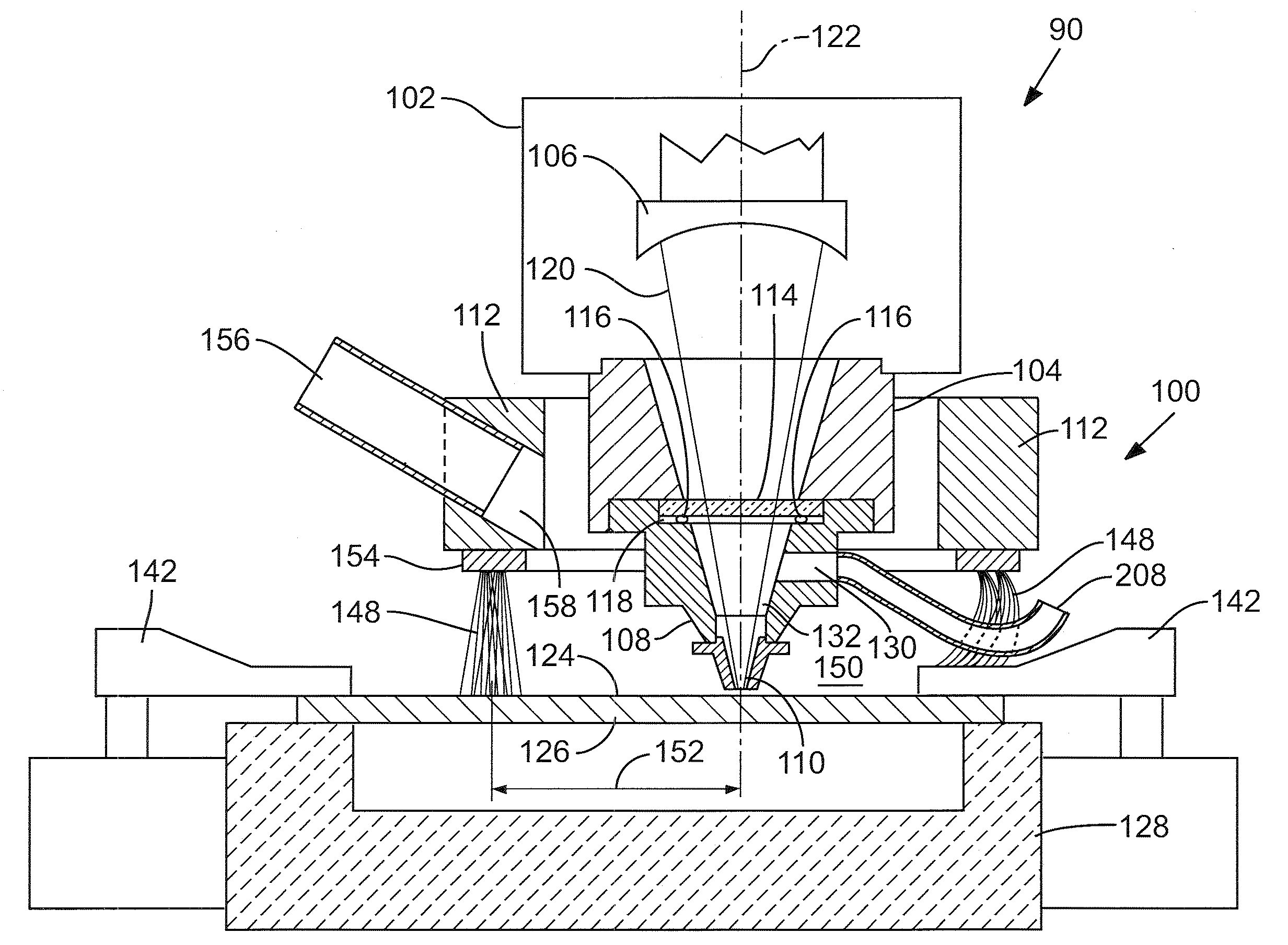
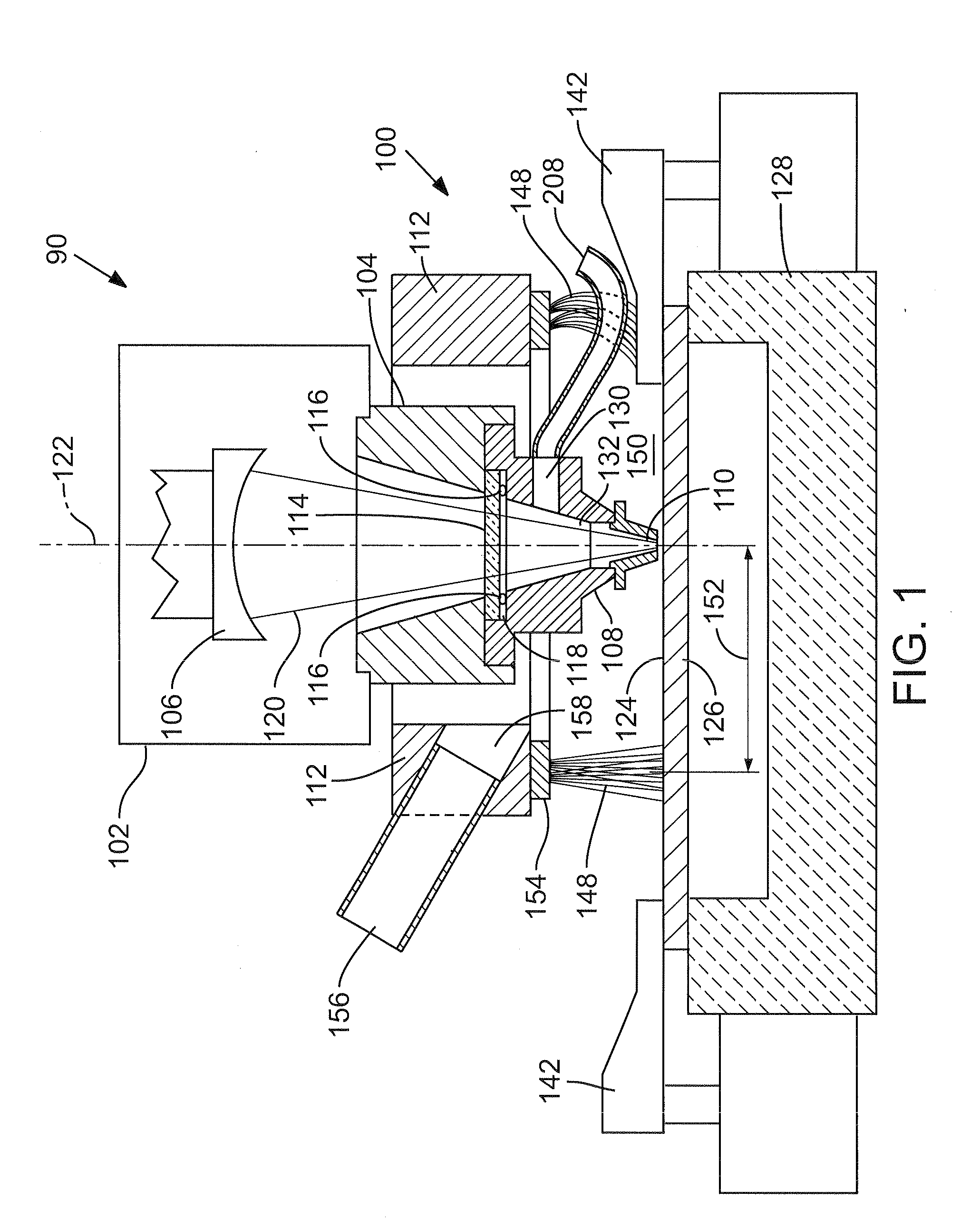
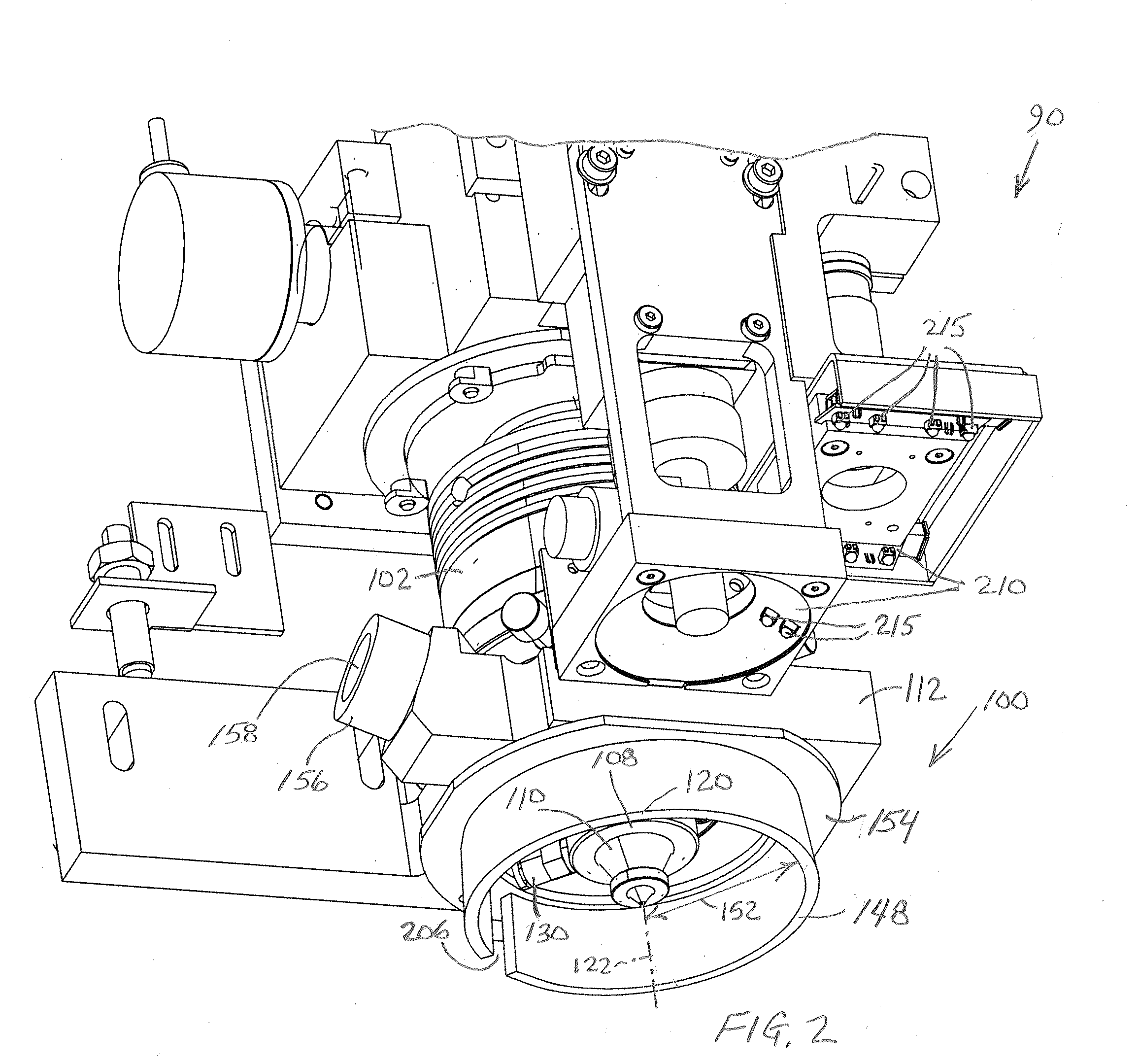
[0014]FIGS. 1-3 show a laser cutting head 90 of a laser micromachining system. Laser cutting head 90 includes laser micromachining-generated debris management (i.e., containment and removal) components 100 associated with a laser focusing lens assembly 102 and a laser cutting head alignment assembly 104 that are adjoined as a unitary structure. Lens assembly 102 includes light beam focusing optical components 106 (shown in FIGS. 1 and 3 collectively as a single lens component), and cutting head alignment assembly 104 includes at its bottom end a nozzle and purge gas mount 108 to which a laser beam and gas flow output nozzle 110 is affixed. A debris removal collar 112 supports cutting head alignment assembly 104 and nozzle and purge gas mount 108. Optical components 106 of lens assembly 102 are positioned safely behind a protective debris window 114 set and sealed by an O-ring 116 in a recess 118 in the top end of nozzle and purge gas mount 108, where it is adjoined with cutting head...


PUM

PropertyMeasurementUnit
Pressureaaaaaaaaaa
Flow rateaaaaaaaaaa
Electrical resistanceaaaaaaaaaa

Abstract

A method of capturing and removing metallic debris created on a target side of a target metal specimen undergoing laser micromachining entails providing a barrier that encompasses the immediate volume surrounding a laser cutting head output nozzle to contain the ejected debris and extracting the debris through a vacuum outlet. A preferred system implementing this approach to debris management includes a barrier in the form of a flexible fiber brush configured in the shape of a ring and positioned to trap ejected debris within a localized area surrounding a target area where the laser beam is incident on the target metal specimen. The ring brush is made of material that is robust to molten metals. An inert gas directed at a high flow rate along the target surface of the metal specimen carries ejected surface debris trapped in the ring brush toward a vacuum outlet.

Description

RELATED APPLICATION[0001]This application claims benefit of U.S. Provisional Patent Application No. 61 / 073,672, filed Jun. 18, 2008.COPYRIGHT NOTICE[0002]© 2008 Electro Scientific Industries, Inc. A portion of the disclosure of this patent document contains material that is subject to copyright protection. The copyright owner has no objection to the facsimile reproduction by anyone of the patent document or the patent disclosure, as it appears in the Patent and Trademark Office patent file or records, but otherwise reserves all copyright rights whatsoever. 37 CFR §1.71(d).TECHNICAL FIELD[0003]The system disclosed addresses management of debris generated by laser processing and, more specifically, by laser micromachining of small-scale target specimen features.BACKGROUND INFORMATION[0004]Machining metals and other target specimens using a laser beam generates a significant amount of molten debris. Most of the debris is ejected from the immediate region surrounding the laser cut, as t...

Claims


Application Information

Patent Timeline
IPC IPC(8): B23K26/16
CPCB23K26/14B23K26/16B23K26/147
Inventor KOSMOWSKI, MARK T.
Owner ELECTRO SCI IND INC
Why Eureka
Try Eureka