Actuating solenoid and non-stick disk

a solenoid and non-stick technology, applied in the direction of magnets, operating means/release devices of valves, magnetic bodies, etc., can solve the problem that the oil equalization cannot be performed at the requisite speed by means, and achieve the effect of minimizing the time of disabling

Active Publication Date: 2009-12-24
ROBERT BOSCH GMBH
View PDF9 Cites 8 Cited by
  • Summary
  • Abstract
  • Description
  • Claims
  • Application Information

AI Technical Summary

Benefits of technology

[0006]An aspect of the present invention is to provide an actuating solenoid as well as a non-stick disk suitable for such an actuating solenoid, with which the disabling times can be minimized.

Problems solved by technology

In actual practice, it has proven that this oil equalization cannot be performed at the requisite speed by means of the above-mentioned solutions.

Method used


Image

  • Actuating solenoid and non-stick disk
  • Actuating solenoid and non-stick disk
  • Actuating solenoid and non-stick disk

Examples


Embodiment Construction

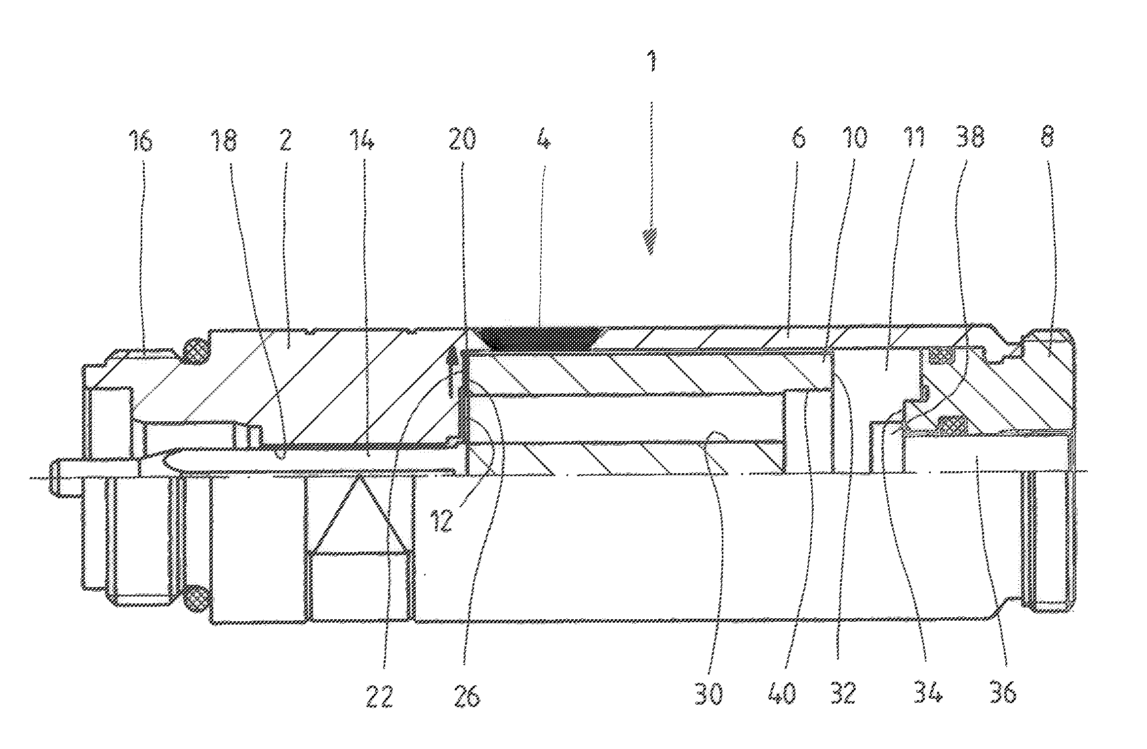
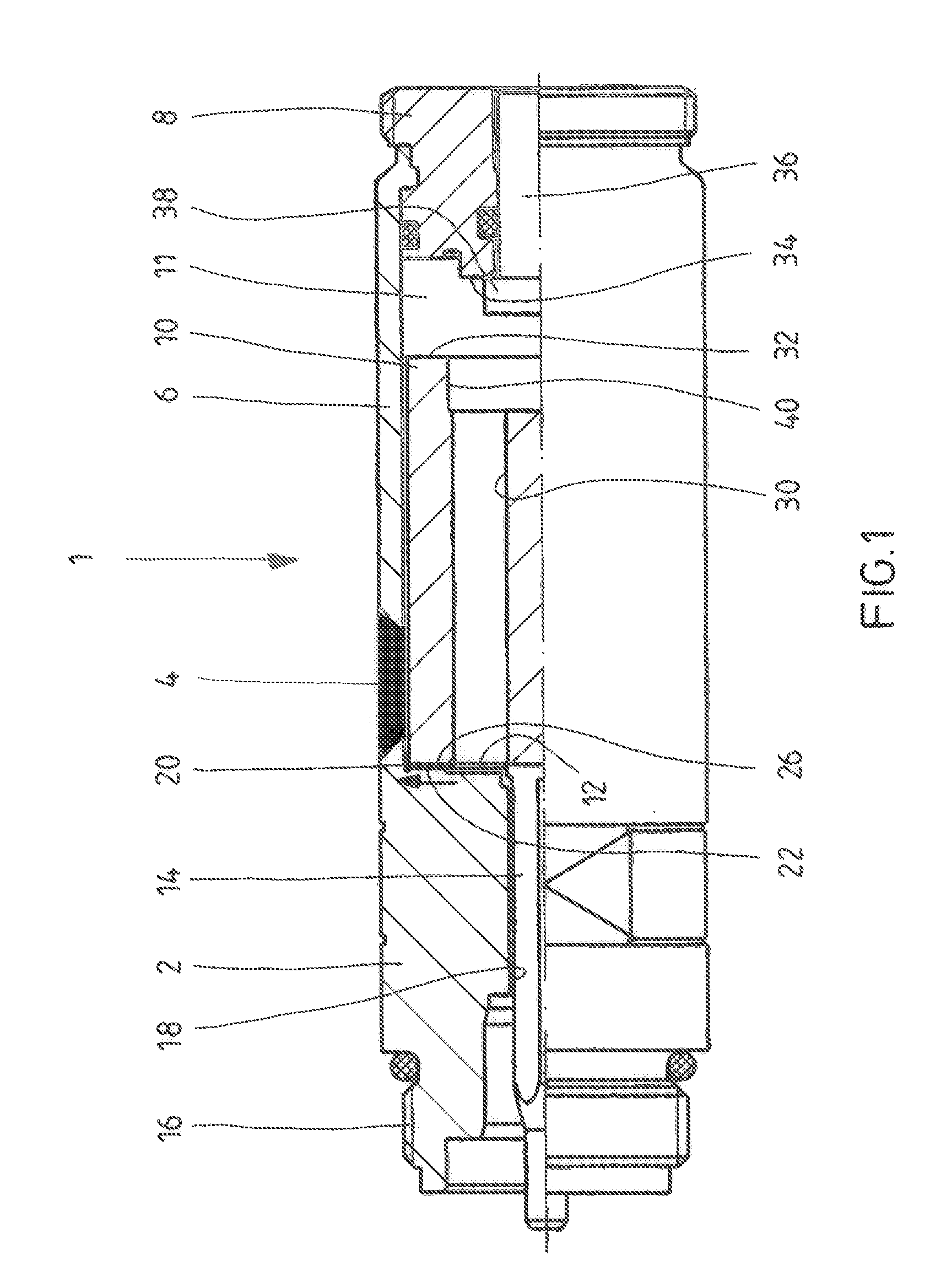
[0025]FIG. 1 shows part of a longitudinal section through a pole tube 1 of an actuating solenoid having a pressure-tight design. The pole tube 1 consists essentially of a pole core 2, a separating ring 4 and a tube piece 6 that is closed off by means of a closure piece 8. In the embodiment shown, this closure piece 8 is joined to the tube piece 6 by shaping, for example, by rolling or crimping, and serves to limit the stroke of an armature 10 that is accommodated so as to be axially movable in an armature space 11 that has an air gap 12 and that is delimited by the pole core 2, the pole piece 6 and the closure piece 8. A tappet 14 is attached to the armature 10, it passes through the pole core 2 in the axial direction and it is directly or indirectly joined to a control spool of a valve in order to actuate the latter. In principle, it is also possible to configure the tappet 14 as a separate component so that the armature 10 then strikes against the tappet 14.

[0026]The end section o...


PUM


Abstract

An actuating solenoid and a non-stick disk by means of which adhesion of an armature of an actuating solenoid to a pole core can be prevented. The non-stick disk is provided with at least one oil channel through which oil can be fed into the contact area between the non-stick disk and the armature or the pole core.

Description

[0001]Priority is claimed to German Patent Application No. DE 10 2008 029 979.0, filed Jun. 24, 2008, the contents of which are hereby incorporated by reference in their entirety.FIELD OF THE INVENTION[0002]The present invention relates generally to an actuating solenoid and a non-stick disk for an actuating solenoid. More specifically, the present present invention relates to an actuating solenoid and a non-stick disk by means of which adhesion of an armature of an actuating solenoid to a pole core can be prevented.BACKGROUND OF THE INVENTION[0003]An actuating solenoid of the generic type is employed, for example, as a solenoid actuator or proportional solenoid for directional control valves in order to adjust their valve spools. The basic structure of such an actuating solenoid is explained, for example, in WO 99 / 62084. According to this publication, an actuating solenoid has a pole tube that accommodates an armature which can be moved axially and by means of which the valve spool...

Claims


Application Information

Patent Timeline
Patent Type & Authority Applications(United States)
IPC IPC(8): F16K31/02
CPCF16K31/0675F16K31/0693H01F2007/1661H01F2007/085H01F7/1607
Inventor BECK, THORSTENKISSNER, MATTHIAS
Owner ROBERT BOSCH GMBH
Why Eureka
Try Eureka