Clock Generator Circuit for a Charge Pump

a generator circuit and charge pump technology, applied in the direction of dc-dc conversion, power conversion systems, instruments, etc., can solve the problems of pump power consumption, current generation and corresponding power consumption, and achieve the effect of reducing power consumption

Active Publication Date: 2009-12-24
SANDISK TECH LLC
View PDF100 Cites 72 Cited by
  • Summary
  • Abstract
  • Description
  • Claims
  • Application Information

AI Technical Summary

Benefits of technology

The technical effect of this patent is to reduce power consumption in a charging device by adjusting the speed of its internal clock based on the amount of electricity it receives from an external source.

Problems solved by technology

The technical problem addressed in this patent text relates to improving the design of charge pumps to decrease their size and current consumption while maintaining efficient operation. Specifically, it focuses on reducing the impact of parasitic capacitance caused by the clock signals used to drive the pump's stages.

Method used


Image

  • Clock Generator Circuit for a Charge Pump
  • Clock Generator Circuit for a Charge Pump
  • Clock Generator Circuit for a Charge Pump

Examples


Embodiment Construction

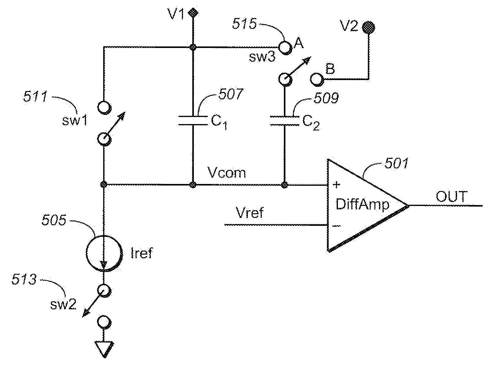
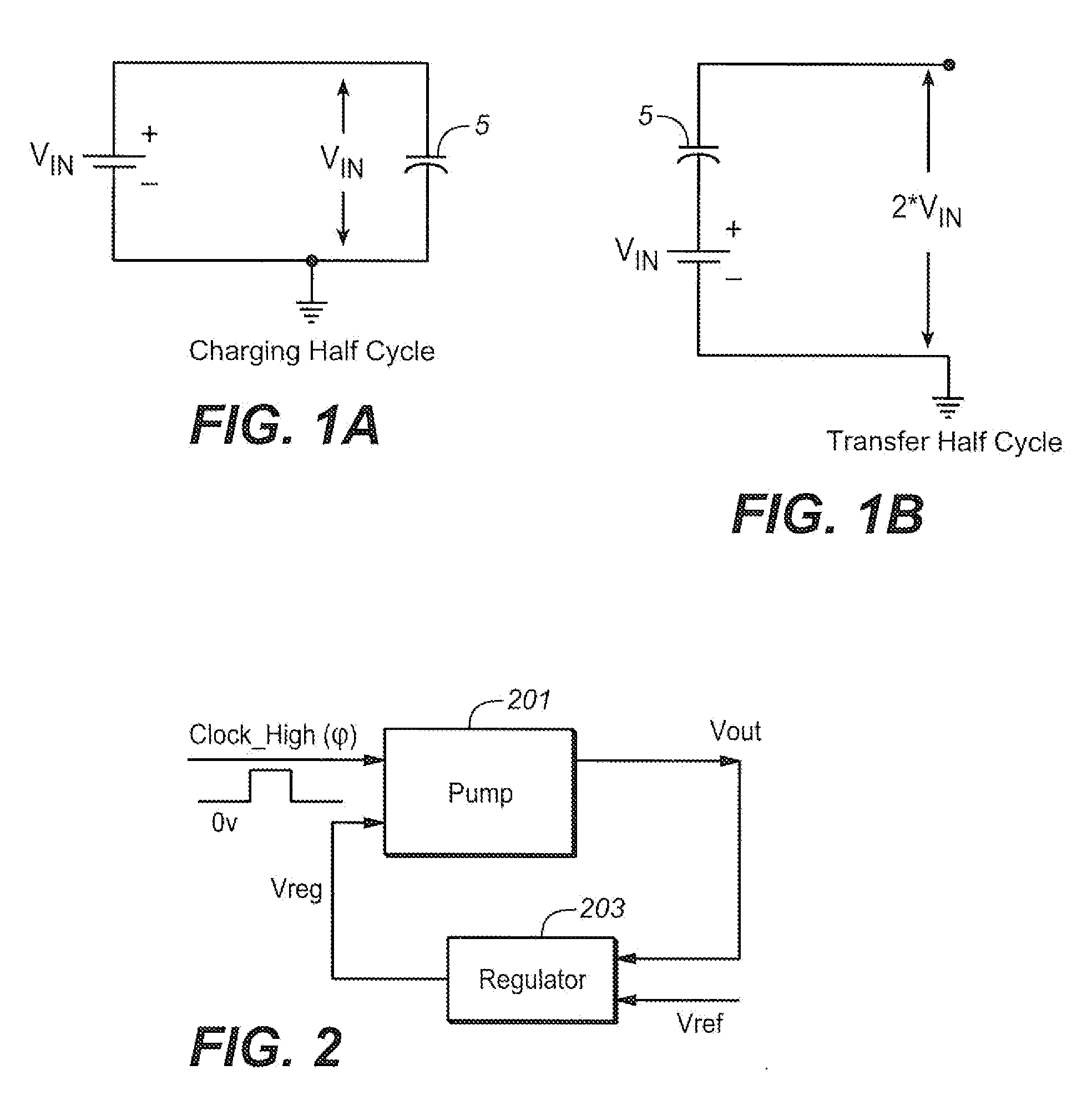
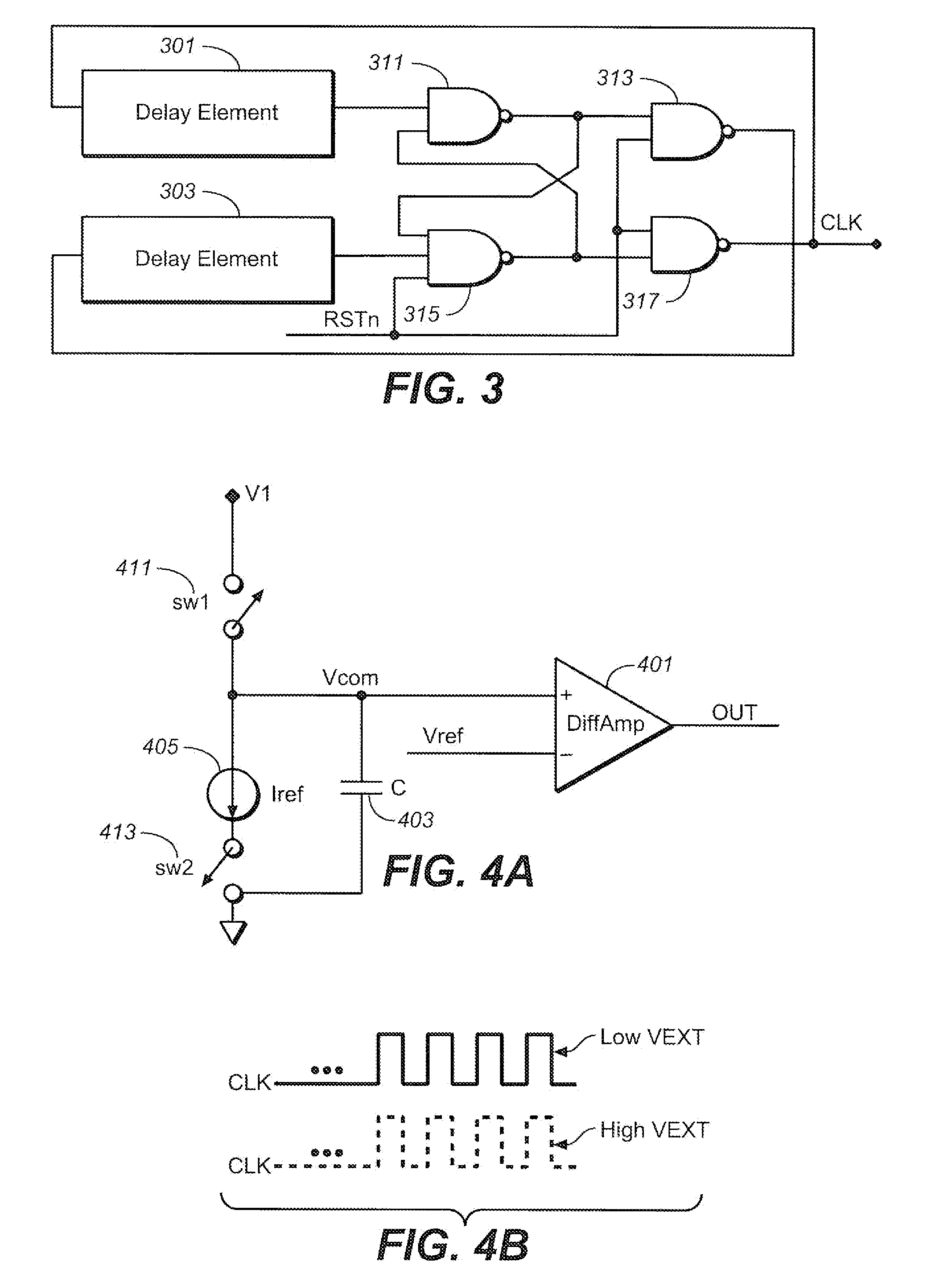
[0016]The typical pump design uses a constant clock frequency across supply voltage levels. As noted in the Background, as the supply voltage increases, because of clock driver parasitics, the pump consumes more power. To ameliorate this, the following presents a clock generator design that tracks the clock driver period with the external pump supply voltage. More specifically, the clock generator will have a frequency that is a decreasing function of the supply voltage, so that as the supply voltage increases, the frequency will decrease and vice versa. Consequently, the design will save on pump power consumption while maintaining the pump's I-V curve.

[0017]More information on charge pumps, such Dickson type pumps and charge pumps generally, can be found, for example, in “Charge Pump Circuit Design” by Pan and Samaddar, McGraw-Hill, 2006, or “Charge Pumps: An Overview”, Pylarinos and Rogers, Department of Electrical and Computer Engineering University of Toronto, available on the w...


PUM


Abstract

A charge pump system is formed on an integrated circuit that can be connected to an external power supply. The system includes a charge pump and a clock generator circuit. The clock circuit is coupled to provide a clock output, at whose frequency the charge pump operates and generates an output voltage from an input voltage. The clock frequency is a decreasing function of the voltage level of the external power supply. This allows for reducing power consumption in the charge pump system formed on a circuit connectable to an external power supply.

Description


Claims


Application Information

Patent Timeline
Owner SANDISK TECH LLC
Why Eureka
Try Eureka