Print head

a printing head and printing head technology, applied in the field of printing heads, can solve the problems of reducing the size of the nozzle, preventing the supply of the amount of droplets per unit area, and limiting the resolution of the nozzle row, so as to improve the impact accuracy of ejecting droplets, improve the quality of printed images, and improve the effect of printing speed

Active Publication Date: 2009-12-24
CANON KK
View PDF14 Cites 18 Cited by
  • Summary
  • Abstract
  • Description
  • Claims
  • Application Information

AI Technical Summary

Benefits of technology

[0016]The present invention has been made in view of the above-described problems. An object of the present invention is to, in response to a demand for improvement of image quality and print speed, improve the impact accuracy of ejected droplets to increase the quality of printed images and the print speed.
[0018]According to the present invention, when the print head ejects droplets, a bubble generated by the print element is inhibited from being deformed during the ejection of the droplet. Thus, the ejected droplet is prevented from being affected by the deformation of the bubble. Consequently, the droplet can be accurately ejected to a predetermined position.

Problems solved by technology

However, when droplets of a reduced size are ejected, as is, a reduced amount of droplets are ejected, preventing supplying of an amount of droplets required per unit area sufficiently.
However, the increase in nozzle row resolution is limited.
In general, a further reduction in the size of the droplets ejected is known to reduce ejection efficiency with respect to the droplet ejected.
Then, that makes it difficult to connect between wiring and the heaters.
Finally, the heaters cannot be arranged in a line.
However, in spite of these measures, the quality of images resulting from printing may be degraded.
Since the ink in the ink channel has difficulty moving, when an energy generating element is driven inside the pressure chamber, the resulting bubbling energy is inhibited from escaping toward the common liquid chamber.
Also disadvantageously, if the size of satellite droplets continues to decrease in connection with the recent decrease in the size of ejected droplets, the satellite droplets fly in and around the printing apparatus and may adhere to the apparatus.
The satellite droplets adhering to the printing apparatus disadvantageously contaminates the interior of the apparatus.

Method used


Image

  • Print head
  • Print head
  • Print head

Examples


first embodiment

[0032]A first embodiment of the present invention will be described below in detail with reference to the accompanying drawings.

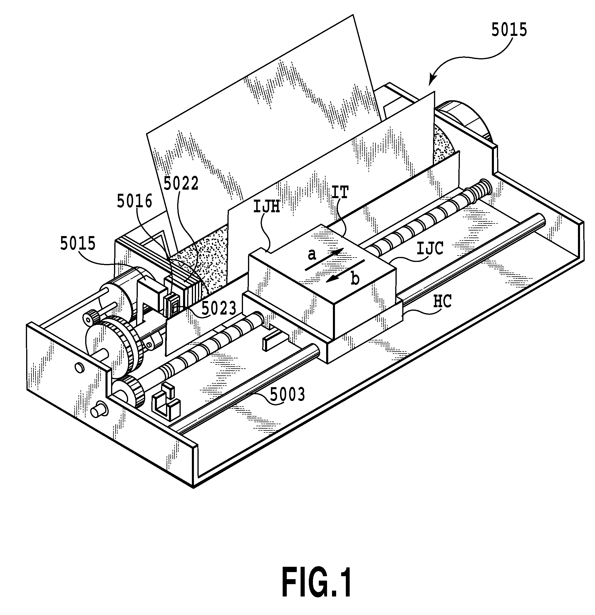
[0033]FIG. 1 is a perspective view of an ink jet printing apparatus IJRA using a print head as an ink jet print head according to an embodiment of the present invention. The ink jet printing apparatus IJRA shown in FIG. 1 includes a carriage HC. An ink jet cartridge IJC is mounted on a carriage HC. In the present embodiment, the ink jet cartridge IJC contains a print head IJH and an ink tank IT which are integrated together. Though, in the present embodiment, the ink jet cartridge IJC contains the print head IJH and ink tank IT integrated together, but the present invention is not limited to this aspect. The print head IJH and the ink tank IT may be formed to be separable so as to be assembled together before use. The carriage HC is supported on a guide rail 5003 so as to be movable in a direction in which the guide rail 5003 extends. For printing, the carr...

second embodiment

[0065]Now, a second embodiment of the present invention will be described with reference to FIGS. 7A to 7C. Components of the second embodiment which can be configured as is the case with the first embodiment are denoted, in the figures, by the same reference numerals and will not be described below. Only differences from the first embodiment will be described below.

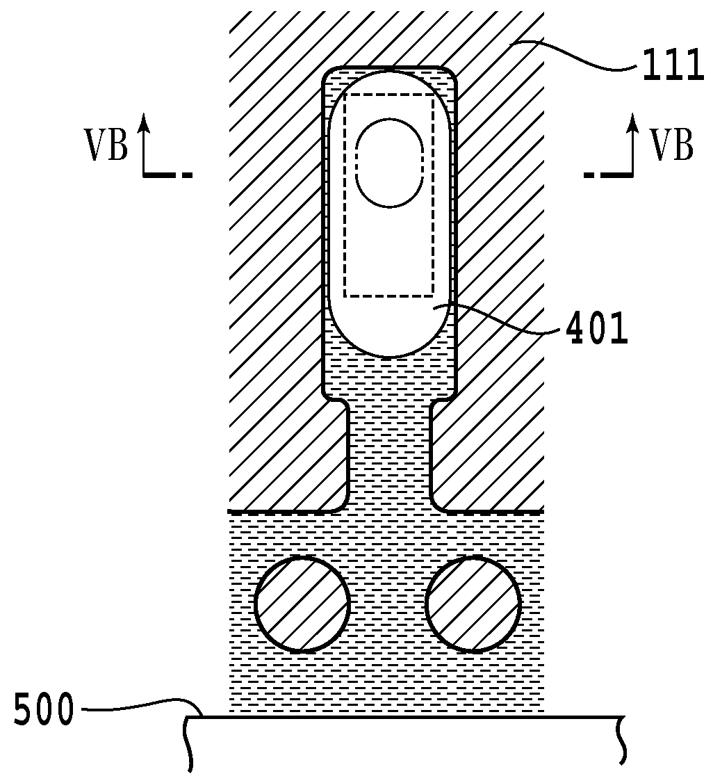
[0066]FIGS. 7A to 7C show the nozzle structure of a print head IJH′ according to the second embodiment of the present invention. FIG. 7A is a sectional view of the interior of four of a plurality of nozzles in the ink jet print head IJH′ as viewed in the ink ejection direction. FIG. 7B is a sectional view taken along line VIIB-VIIB in FIG. 7A. FIG. 7C is a sectional view taken along line VIIC-VIIC in FIG. 7A.

[0067]The print head IJH′ according to the second embodiment differs from the print head according to the first embodiment in that two types of a plurality of pressure chambers are staggeredly arranged on one side of...

third embodiment

[0082]Now, a print head IJH″ according to a third embodiment of the present invention will be described with reference to FIGS. 8A to 8C. Components of the third embodiment which can be configured as is the case with the first and second embodiments are denoted, in the figures, by the same reference numerals and will not be described below. Only differences from the first and second embodiments will be described below.

[0083]FIGS. 8A to 8C show the nozzle structure of the ink jet print head according to the third embodiment of the present invention. FIG. 8A is a sectional view of an essential part of the print head IJH″ as viewed in the ink ejection direction, the view showing the interior of the print head. FIG. 8B is a sectional view taken along line VIIIB-VIIIB in FIG. 8A. FIG. 8C is a sectional view taken along line VIIIC-VIIIC in FIG. 8A.

[0084]In the print head IJH″ according to the third embodiment, a first pressure chamber has a main pressure chamber 210 in which a print eleme...


PUM


Abstract

A present invention improves the impact accuracy of ejected droplets, the quality of printed images, and print speed. A print head according to the present invention has an ink channel for which the width thereof in a direction orthogonal to an ink supply direction in which ink is supplied from an ink supply port to a pressure chamber is smaller than that of a pressure chamber. In the print head, the center of a heater along the ink supply direction is offset from the center of the pressure chamber along the ink supply direction, toward the side of the pressure chamber far from the ink supply port in the ink supply direction.

Description

BACKGROUND OF THE INVENTION[0001]1. Field of the Invention[0002]The present invention relates to a print head that ejects a liquid onto a print medium.[0003]2. Description of the Related Art[0004]In recent years, ink jet printing apparatuses have been prevailing rapidly in which a print head is located opposite a print medium to eject ink droplets onto the print medium for printing. The ink jet printing apparatuses have the advantages of being easily miniaturized and being able to relatively easily perform color printing. An ink jet printing apparatus is disclosed in, for example, Japanese Patent Laid-Open No. H04-10941 (1992). Such an ink jet printing apparatus uses any of various techniques for improving the quality of images resulting from printing.[0005]When the ink jet printing apparatus is used for printing, a dot density control method can be used for printing; the dot density control method controls the number of print dots of a given size provided per unit area in order to ...

Claims


Application Information

Patent Timeline
IPC IPC(8): B41J2/135
CPCB41J2/14112B41J2202/11B41J2002/14403B41J2002/14185
Inventor OIKAWA, MASAKITOMIZAWA, KEIJIUMEYAMA, MIKIYAYAMANE, TORUAKAMA, YUICHIROMURAOKA, CHIAKIKURODA, TOMOTSUGUNAGATA, SHINGOKUDO, SATOSHI
Owner CANON KK
Why Eureka
Try Eureka