Light guide plate, light guide plate assembly, and planar lighting device and liquid crystal display device using these

a technology of light guide plate and assembly, which is applied in the direction of lighting and heating apparatus, instruments, mechanical apparatus, etc., can solve the problems of limit to thinning, and achieve the effects of reducing light use efficiency, reducing weight, and improving performan

Active Publication Date: 2009-12-24
FUJIFILM CORP
View PDF4 Cites 96 Cited by
  • Summary
  • Abstract
  • Description
  • Claims
  • Application Information

AI Technical Summary

Benefits of technology

[0051]With the light guide plate assembly of the first aspect of the present invention and the planar lighting device of the second aspect of the present invention, by using the light guide plate having the thickness of the light entrance plane made small in the direction perpendicular to the light exit plane and made larger in the light advancing direction, and the prism sheet having the defined vertex angle of the prism and the prism disposed to face the light guide plate, the light entering through the light entrance plane can be caused to reach a farther position, thereby enabling emission of a uniform illumination light having no brightness unevenness without reducing light use efficiency, in other words, enabling emission with high light use efficiency and high front brightness. Besides, the light guide plate assembly and the planar lighting device can be thinned, reduced in weight, and enlarged.
[0052]Further, according to the present invention, by the configuration of the fewer number of components compared with the light guide plate assembly and the planar lighting device of the conventional art, it is possible to obtain the light guide plate assembly and the planar lighting device having higher performance compared with the conventional art and the above-mentioned effects at low cost.
[0053]The light guide plate of the third aspect of the present invention includes the light exit plane having the rectangular outer shape, the four light entrance planes connected to the four sides of the light exit plane and substantially orthogonal to the light exit plane, and the backside op

Problems solved by technology

However, in the BLU of the direct type, a direct light from the fluorescent tubes is converted into a uniform planar light source, and thus there is a problem in th

Method used


Image

  • Light guide plate, light guide plate assembly, and planar lighting device and liquid crystal display device using these
  • Light guide plate, light guide plate assembly, and planar lighting device and liquid crystal display device using these
  • Light guide plate, light guide plate assembly, and planar lighting device and liquid crystal display device using these

Examples


Embodiment Construction

[0111]A light guide plate, a light guide plate assembly, and a planar lighting device and a liquid crystal display device using these are described below in detail by way of preferred embodiments illustrated in attached drawings.

[0112]First, referring to FIGS. 1A to 17, a light guide plate assembly of the first aspect of the present invention, a planar lighting device of the second aspect of the present invention using the same, and a liquid crystal display device of the fifth aspect of the present invention are described.

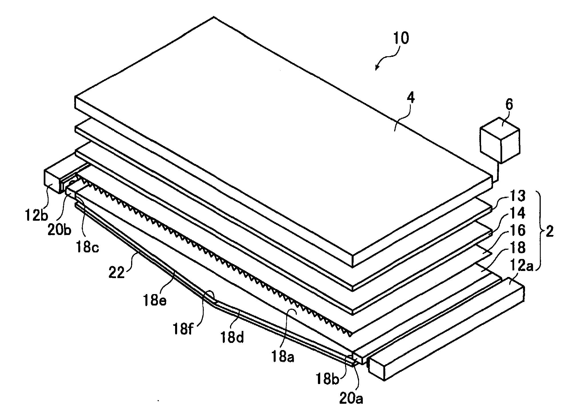
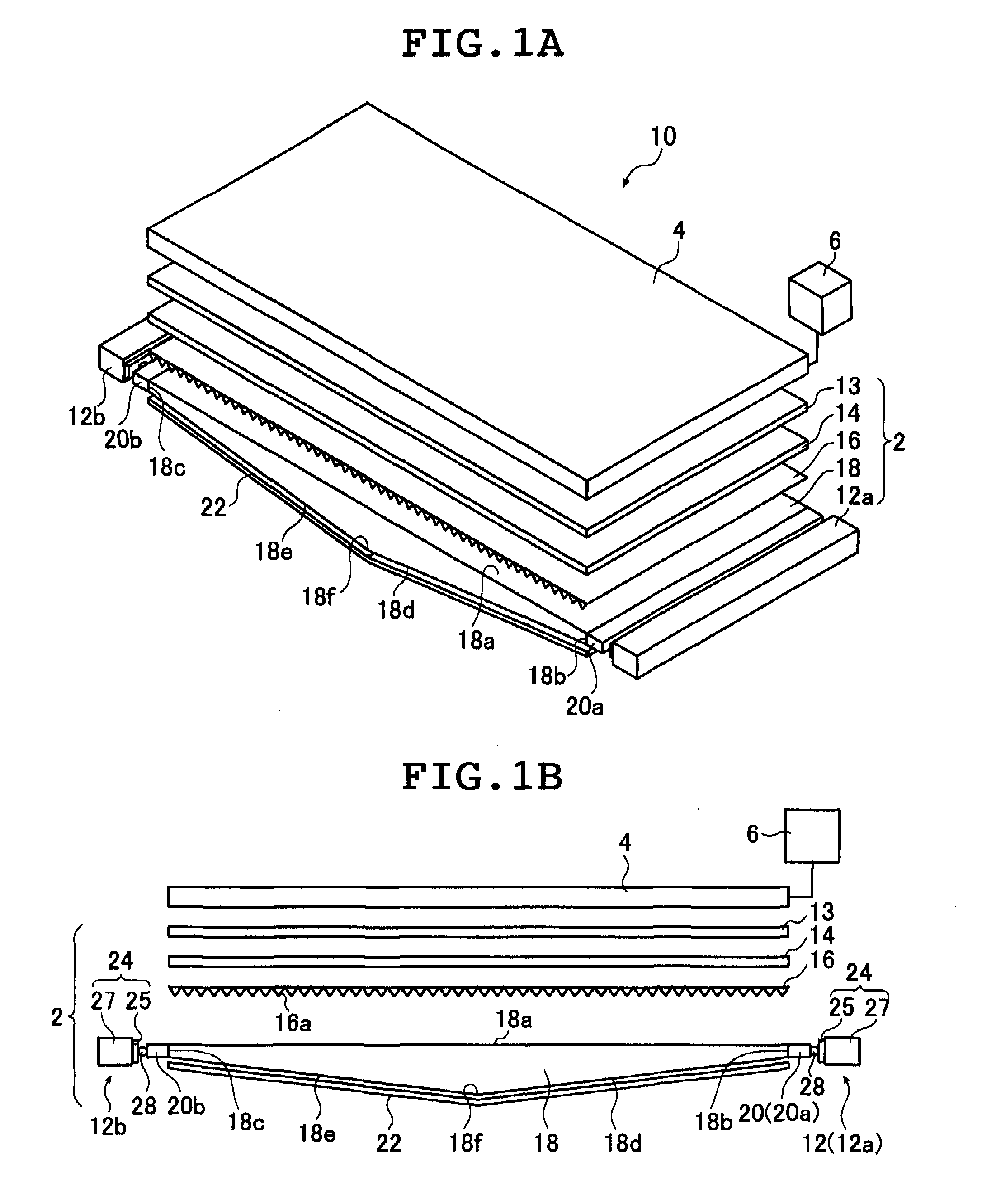
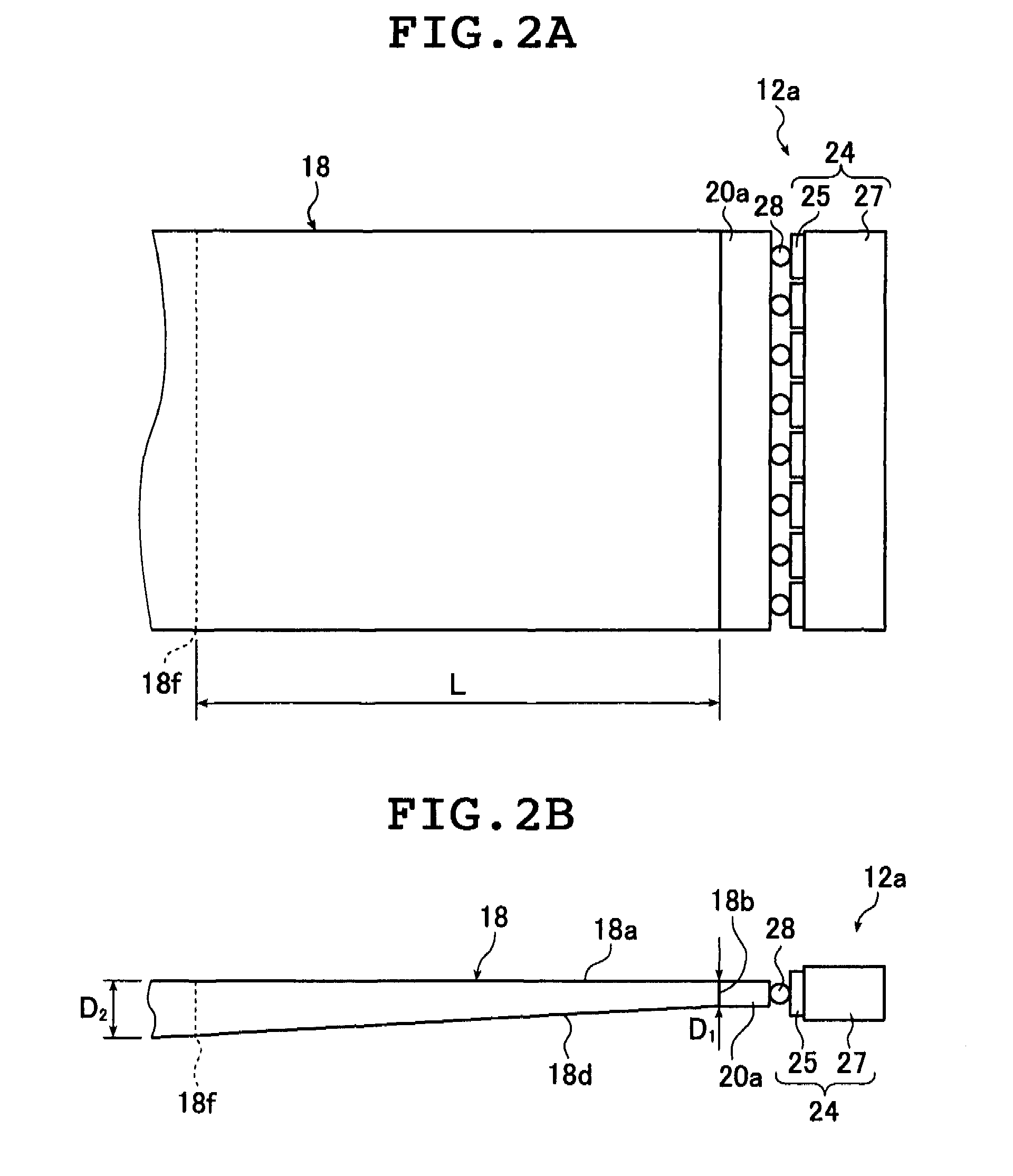
[0113]FIG. 1A is a perspective view schematically illustrating a liquid crystal display device according to an embodiment of the present invention, which includes a planar lighting device according to an embodiment of the present invention using a light guide plate assembly according to an embodiment of the present invention, and FIG. 1B is a schematic sectional view of the liquid crystal display device illustrated in FIG. 1A. FIG. 2A is a schematic partial plan vi...


PUM


Abstract

A light guide plate includes a light exit plane and a light entrance end, is formed into a shape having a thickness in a direction orthogonal to the light exit plane, the thickness being gradually larger as being farther-from the light entrance end, and contains scattering particles dispersed therein, and a light guide plate assembly includes the light guide plate and a prism sheet which includes a plurality of prisms arrayed in parallel with each other, and is arranged so that vertex angles of the prisms face the light exit plane. The scattering particles scatter light entering from the light entrance end and propagating in the light guide plate, which satisfy Expressions (1) and (2) below, and vertex angles of the prisms of the prism satisfy Expression (3) and (4) below.
1.1≦ΦNPLGKC≦8.2   (1)
0.005≦KC≦0.1   (2)
55°≦θ≦80°  (3)
0°≦θ1≦15° and 30°≦θ2≦45°  (4)

Description

TECHNICAL FIELD [0001]The present invention relates to a light guide plate for converting a light of a light source such as a point-like light source or a linear light source into a planar light, a light guide plate assembly for diffusing a light emitted from the light source to emit an illumination light from a light exit plane, and a planar lighting device and a liquid crystal display device using these. More specifically, the present invention relates to a light guide plate for emitting a uniform planar illumination light of a large lighting area, a light guide plate assembly capable of maximizing light use efficiency and front brightness, a planar lighting device having a large lighting area and high in-plane uniformity for indoor and outdoor lighting, or a planar lighting device used as a backlight for a liquid crystal display panel of a liquid crystal display device, an advertisement panel an advertisement tower, or a billboard, and a large-screen liquid crystal display device...

Claims


Application Information

Patent Timeline
IPC IPC(8): G02F1/13357G02B5/02F21V5/02F21V8/00
CPCG02B5/021G02B5/0242G02B5/0263G02B5/0268G02B5/0278G02B6/0085G02B6/0043G02B6/0053G02B6/0061G02B6/0068G02B5/045
Inventor OKUMURA, TAKAMITSUENDO, TOSHIAKI
Owner FUJIFILM CORP
Why Eureka
Try Eureka