Illumination device and projection display device using the same
a technology of projection display and projection device, which is applied in the direction of instruments, lighting and heating equipment, fibre light guides, etc., can solve the problems achieve the effects of reducing light use efficiency, high light use efficiency, and reducing use efficiency
- Summary
- Abstract
- Description
- Claims
- Application Information
AI Technical Summary
Benefits of technology
Problems solved by technology
Method used
Image
Examples
first exemplary embodiment
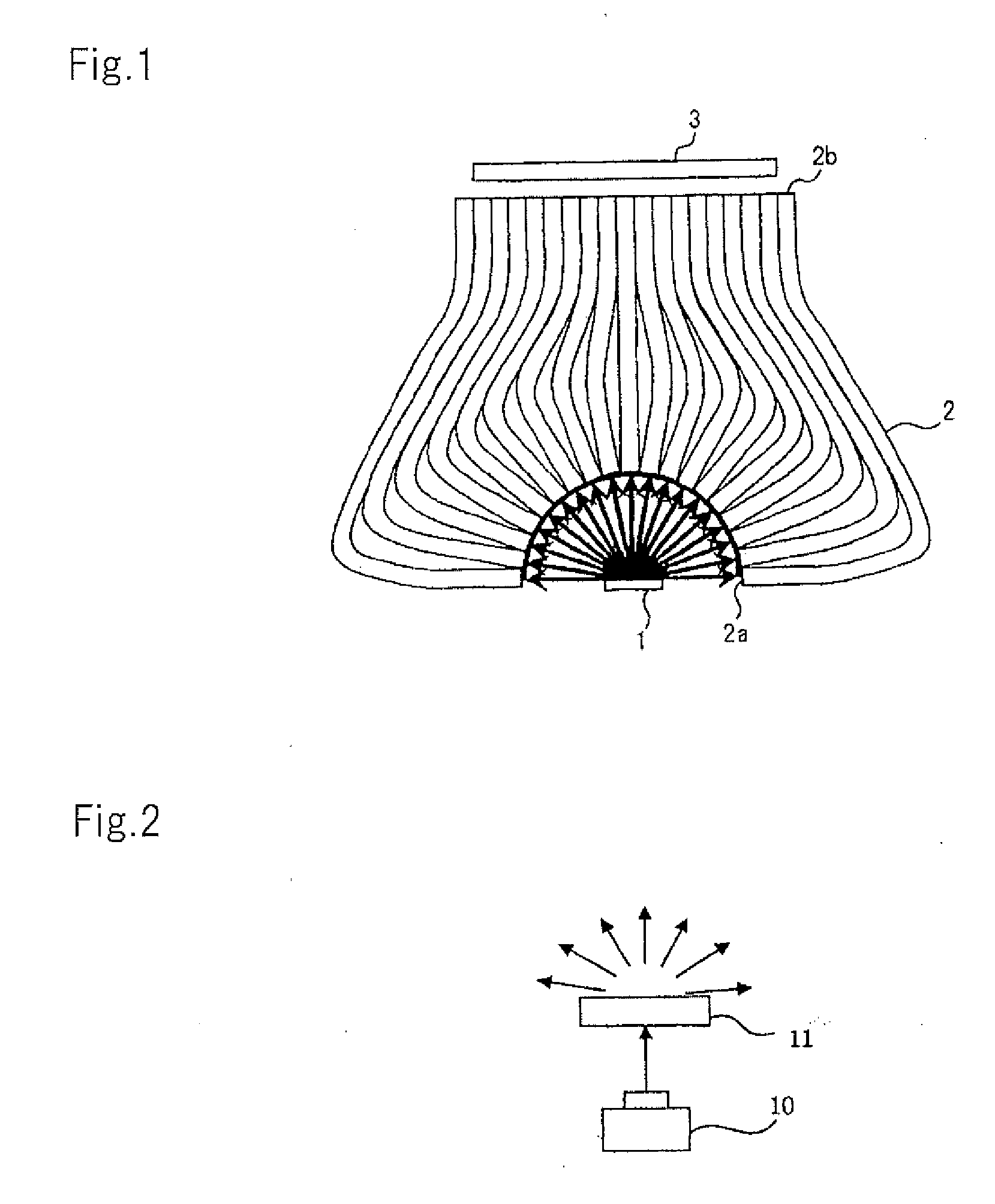
[0028]FIG. 1 is a schematic view showing the configuration of an illumination device according to the first exemplary embodiment of the present invention.
[0029]Referring to FIG. 1, the illumination device, which is used for a projection display device such as a projector, includes light source 1 that is configured to emit diffused light, and a plurality of light guiding bodies 2 that are configured that the light emitted by light source 1 is entered to one end surface 2a and the light is exited from other end surface 2b. End surface 2a of each light guiding body 2 is formed into a concave shape, and end surface 2b is formed into a planar shape. The arrangement of the concave shape includes not only a curved shape but also a folded shape.
[0030]Light source 1 is, for example, a semiconductor light source such as a light emitting diode
[0031](LED) or a semiconductor laser (LD), a light source referred to as a solid light source, or a light source using a phosphor. As light source 1, a s...
second exemplary embodiment
[0050]An optical fiber includes a core for propagating light, and a clad formed on the outer circumference of the core. When light enters the entire end surface of the optical fiber, the light that entered the clad portion cannot be used, and light loss consequently occurs. A structure that is capable of suppressing the light loss caused by the clad will be described.
[0051]FIG. 5 is a schematic view showing the configuration of an illumination device according to the second exemplary embodiment of the present invention.
[0052]The illumination device of this embodiment is similar to that of the first embodiment except for the inclusion of microlens array 4. In FIG. 5, components similar to those of the first embodiment are denoted by similar reference numerals.
[0053]Microlens array 4 includes a plurality of microlenses provided for each light guiding body 2. Microlens array 4, which is formed into a concave shape, is located to face a concave surface constituted by end surface 2a of e...
third exemplary embodiment
Projection Display Device of Third Exemplary Embodiment
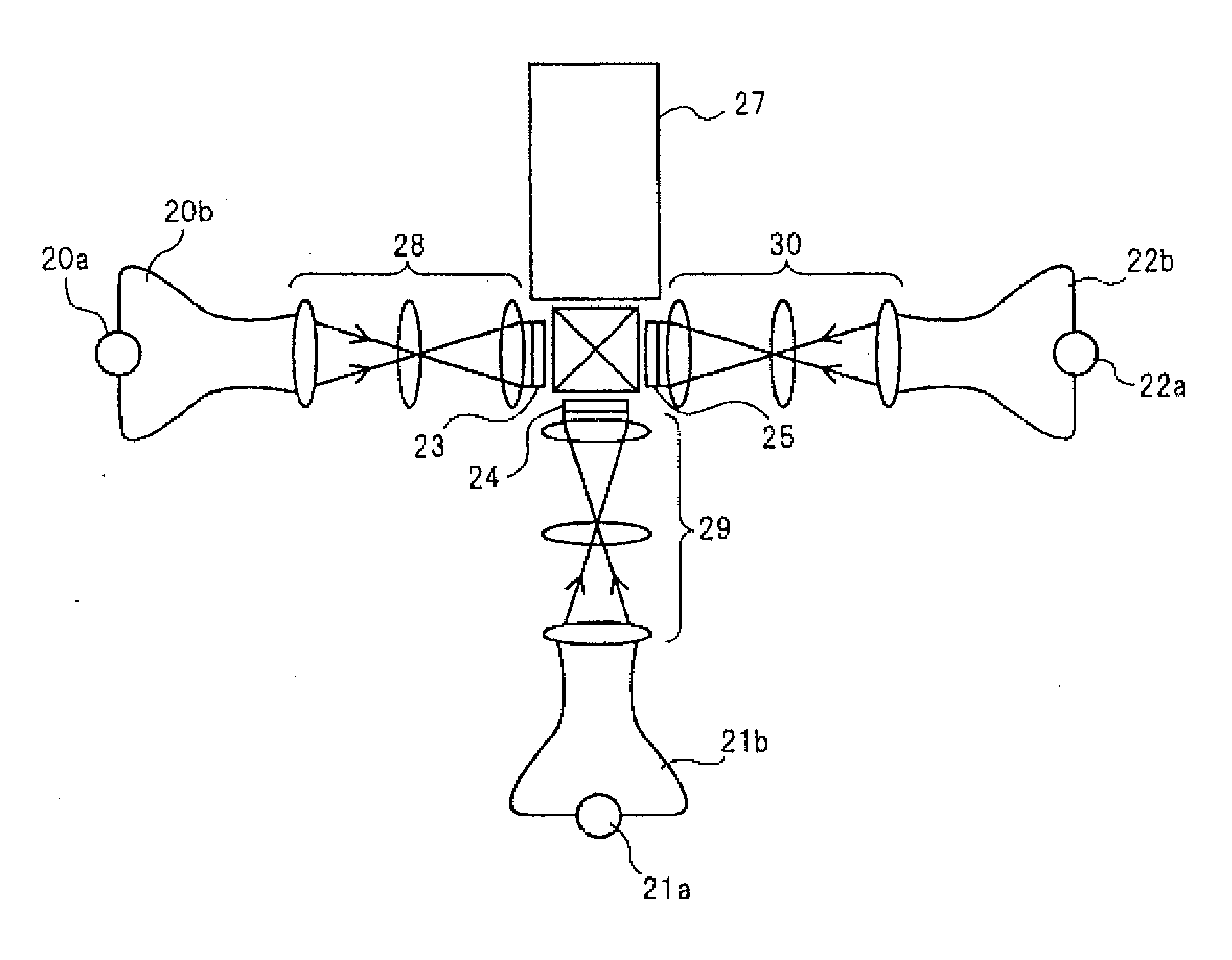
[0084]FIG. 9 is a schematic view showing a projection display device including the illumination device of the present invention according to a third exemplary embodiment.
[0085]Referring to FIG. 9, the projection display device includes illumination devices 20 to 22, lenses 31 to 35, cross dichroic mirror 26, reflective display element 36, and projection optical system 37. Illumination devices 20 to 22 and cross dichroic mirror 26 are similar in configuration to those of the projection display device of the first embodiment.
[0086]Lens 31 is disposed between the exit surface of illumination device 20 and the first incident surface of cross dichroic mirror 26. Lens 32 is disposed between the exit surface of illumination device 21 and the second incident surface of cross dichroic mirror 26. Lens 33 is disposed between the exit surface of illumination device 22 and the third incident surface of cross dichroic mirror 26.
[0087]Lenses 3...
PUM
 Abstract
Description
Claims
Application Information
 - R&D
- Intellectual Property
- Life Sciences
- Materials
- Tech Scout
- Unparalleled Data Quality
- Higher Quality Content
- 60% Fewer Hallucinations
Browse by: Latest US Patents, China's latest patents, Technical Efficacy Thesaurus, Application Domain, Technology Topic, Popular Technical Reports.
© 2025 PatSnap. All rights reserved.Legal|Privacy policy|Modern Slavery Act Transparency Statement|Sitemap|About US| Contact US: help@patsnap.com


