Optical information recording/reproducing apparatus and objective optical system for the same

a technology of optical discs and optical information, applied in the field of optical information recording/reproducing apparatuses, can solve the problems that and the information recording or information reproducing for an optical disc cannot be suitably performed

Inactive Publication Date: 2011-09-22
HOYA CORP
View PDF13 Cites 1 Cited by
  • Summary
  • Abstract
  • Description
  • Claims
  • Application Information

AI Technical Summary

Benefits of technology

[0043]By satisfying the condition (20), it becomes possible to avoid more reliably decrease of the light use efficiency for each of the first and second light beams having the wavelengths λ1 and λ2. When the intermediate term of the condition (20) falls outside of the range defined by the condition (20), the light use efficiency for the first light beam having the wavelength λ1 decreases, which is undesirable.

Problems solved by technology

For this reason, there is a concern that the information recording or the information reproducing might not be suitably performed.
In this case, the information recording or the information reproducing for an optical disc can not be suitably performed.

Method used


Image

  • Optical information recording/reproducing apparatus and objective optical system for the same
  • Optical information recording/reproducing apparatus and objective optical system for the same
  • Optical information recording/reproducing apparatus and objective optical system for the same

Examples


first example

[0148]Hereafter, a first example of the optical information recording / reproducing apparatus 100 is described. The specifications of the objective lens 10 mounted on the optical information recording / reproducing apparatus 100 according to the first example are indicated in the following Table 1. Specifically, Table 1 shows the use wavelength, the focal length, NA and the magnification of the objective lens 10. Various definitions regarding Tables in the first example are also applied to Tables in the other examples.

TABLE 11st laser beam2nd laser beam3rd laser beamWavelength (nm)405660790Focal Length (mm)2.202.362.41NA0.850.600.47Magnification M0.0000.0000.000

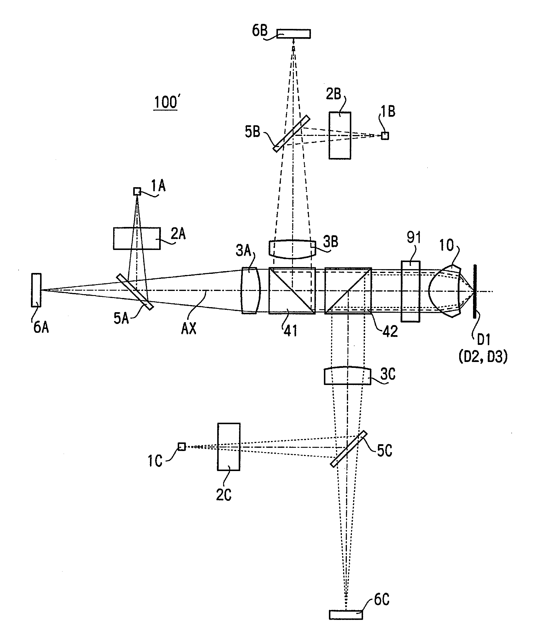
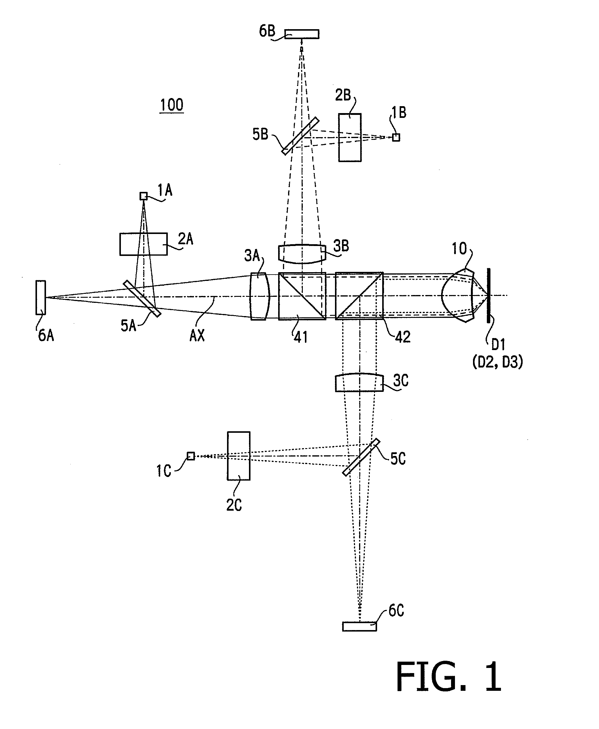
[0149]As shown by the magnification in Table 1, in the optical information recording / reproducing apparatus 100, each of the laser beams used for the respective optical discs D1, D2 and D3 is incident on the objective lens 10 as a collimated beam. Therefore, it is possible to prevent the off-axis aberrations from occurring when th...

second example

[0158]Hereafter, a second example of the optical information recording / reproducing apparatus 100 is described. The objective lens 10 according to the second example has the same numerical configuration as that of the objective lens 10 according to the first example, excepting the blazed wavelengths. Therefore, regarding the specifications of the objective lens 10 according to the second example, the numerical configuration of the optical information recording / reproducing apparatus 100 defined when each of the optical discs D1 to D3 is used, the shape of each aspherical surface, and the coefficients of the optical path difference functions according to the second example, Tables 1 to 6 of the first example are referred to.

[0159]The following Table 11 shows the BD use diffraction order, the DVD use diffraction order, the CD use diffraction order and the blazed wavelengths.

TABLE 11Blazed1st Laser2nd Laser3rd LaserWave-BeamBeamBeamlength(nm)Hmax1(1st1115601.135region)(1)1(1st211405regio...

third example

[0161]Hereafter, a third example of the optical information recording / reproducing apparatus 100 is described. The specifications of the objective lens 10 mounted on the optical information recording / reproducing apparatus 100 according to the third example are indicated in the following Table 15.

TABLE 151st laser beam2nd laser beam3rd laser beamWavelength (nm)405660790Focal Length (mm)2.602.782.83NA0.850.600.47Magnification M0.0000.0000.000

[0162]In the third example, the numerical configuration of optical elements arranged on an optical path along which each laser beam proceeds from the light source to the optical disc is shown. FIG. 10A illustrates a developed optical path defined when the optical disc D1 is used, FIG. 10B illustrates a developed optical path defined when the optical disc D2 is used, and FIG. 10C illustrates a developed optical path defined when the optical disc D3 is used. The numerical configurations of the optical elements arranged on the respective optical paths...


PUM

PropertyMeasurementUnit
wavelengthaaaaaaaaaa

Abstract

An objective optical system for information recording/reproducing, at least one of optical surfaces of the objective optical system comprising a diffraction surface including a first region contributing to converging first, second and third beams and including a diffraction structure formed such that use diffraction orders for the first, second and third beams are 1st-orders and a condition 0.03<(λB11−λ1)/λ1<0.40 is satisfied; a second region contributing to converging only the first and second beams and including a diffraction structure formed such that the use diffraction orders are 1st-orders and a condition: −0.35<(λB12−λB11)/λ1<0.35 is satisfied; and a third region contributing to converging only the first beam and including a diffraction structure formed such that the use diffraction order for the first beam is an odd order and a condition: −0.23<m13×((λB13−λ1)/λ1)<0.23 is satisfied.

Description

BACKGROUND OF THE INVENTION[0001]The present invention relates to an objective optical system for an optical information recording / reproducing apparatus configured to suitably record information to and / or reproduce information from a plurality of types of optical discs based on different standards, and to an optical information recording / reproducing apparatus on which such an objective optical system is mounted.[0002]There exist various standards of optical discs, such as DVD (Digital Versatile Disc) and BD (Blu-ray Disc), differing in recording density, protective layer thickness, etc. Therefore, an objective optical system mounted on the optical information recording / reproducing apparatus is required to have a compatibility with a plurality of types of optical discs. In this case, the term “compatibility” means to guarantee realizing information recording and information reproducing without the need for replacement of components even when the optical disc being used is changed. In...

Claims


Application Information

Patent Timeline
Patent Type & Authority Applications(United States)
IPC IPC(8): G11B7/135G11B7/125
CPCG02B5/1895G11B7/1353G11B7/1275G11B7/13922G11B2007/0006G11B7/1374G11B7/004G11B7/135
Inventor KOREEDA, DAISUKETAKEUCHI, SHUICHI
Owner HOYA CORP
Why Eureka
Try Eureka