Light source device, backlight device, and liquid crystal display device

a technology of light source device and backlight, which is applied in the direction of planar/plate-like light guide, lighting and heating apparatus, instruments, etc., can solve the problems of optical unevenness of light source device, difficult to perform the positioning of each light guide block in the assembling process, and different gaps between light guide blocks, so as to reduce optical unevenness in a surface illuminant, the effect of preventing the displacement or jouncing of light guide elements

Inactive Publication Date: 2009-12-24
SHARP KK
View PDF9 Cites 40 Cited by
  • Summary
  • Abstract
  • Description
  • Claims
  • Application Information

AI Technical Summary

Benefits of technology

[0028]As is described above, in the present light source device which comprises light guide elements tandem arranged, each light guide element is fixed with utilizing a section on which the other light guide element lies. Thereby positional displacement or a jouncing of the light guide elements can be prevented without affecting light emission of the light guide elements. Moreover, optical unevenness in a surface illuminant can be reduced thereby. Further, positioning of each light guide element in such as a housing can be performed easily.

Problems solved by technology

Even if claws are provided on inner walls E3, E4 in x direction, the same problem occurs.
Moreover, it is also a problem that a positioning of each light guide block in an assembling process is difficult to be performed.
When positional relations between each of light guide blocks become uneven, gaps between the light guide blocks also become different.
This leads to optical unevenness of the light source device (surface illuminant).

Method used


Image

  • Light source device, backlight device, and liquid crystal display device
  • Light source device, backlight device, and liquid crystal display device
  • Light source device, backlight device, and liquid crystal display device

Examples


first embodiment

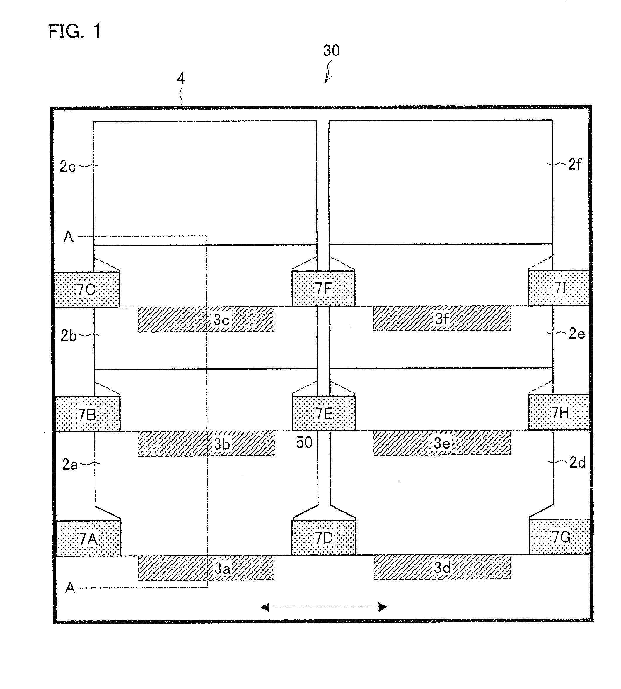
[0065]FIG. 1 is a plan view showing a configuration of a backlight device in a first embodiment. As shown in FIG. 1, a present backlight device 30 includes light guide elements 2 (2a to 2f), light emitting elements 3 (3a to 3f), and a housing 4 provided with ribs 7 (holding ribs 7A to 7I).

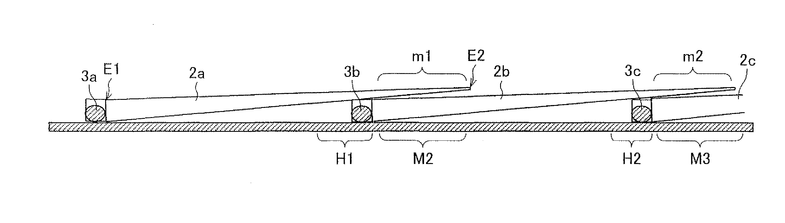
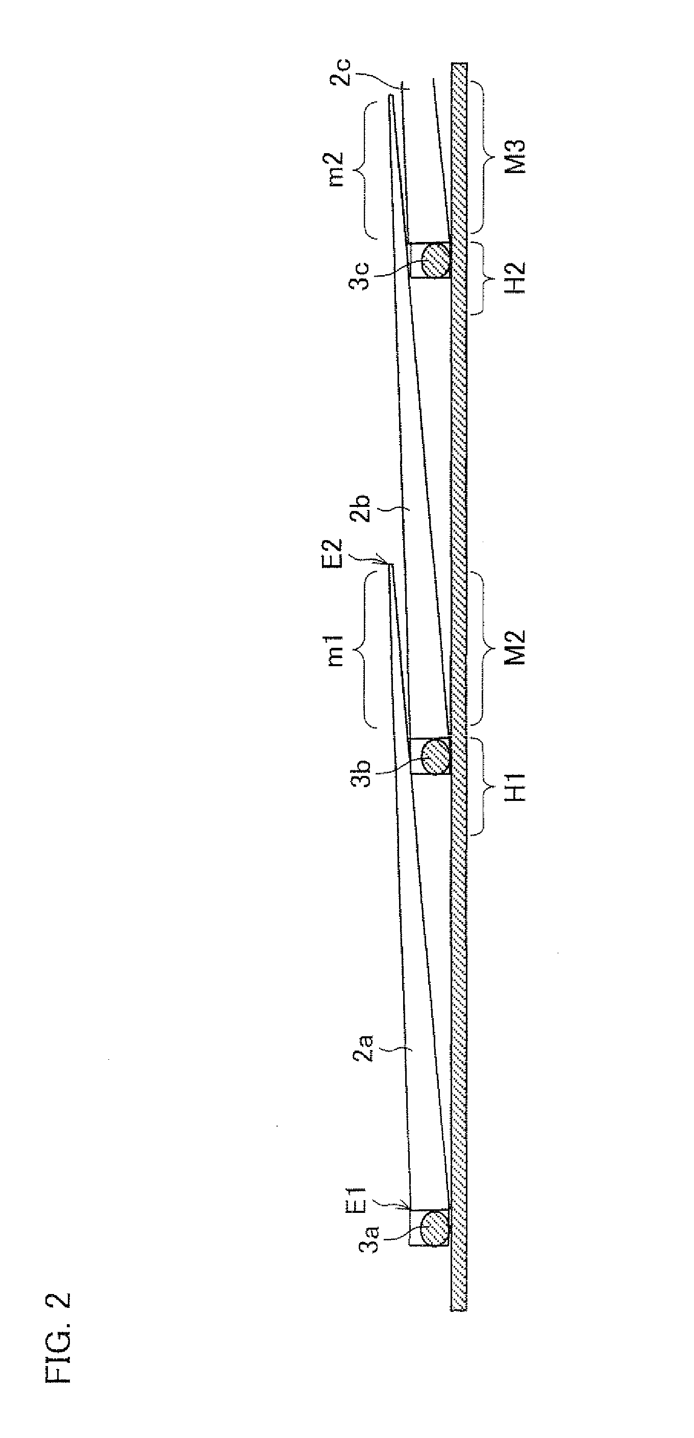
[0066]FIG. 6 shows an arrangement of the light guide elements and the light emitting elements in the present backlight device. As shown in FIG. 6, in the backlight device 30, the light guide elements 2a to 2c are tandem arranged in the lengthwise direction in the figure. The light guide elements 2d to 2f are also arranged in the same way. The light guide elements 2a to 2c are grouped as one group, and also the light guide elements 2d to 2f are grouped as one group. The alignment of the light guide elements 2a to 2c is next to that of the light guide elements 2d to 2f in the crosswise direction. Further, light emitting elements (3a to 3f) are provided for each light guide element (2a to 2f), respect...

second embodiment

[0075]FIG. 10 is a plan view showing a configuration of a backlight device in the second embodiment. FIG. 11 is a cross-sectional view taken along line A-A of FIG. 10. FIG. 12 is a plan view showing an arrangement of light guide elements and light emitting elements in a present backlight device. As shown in FIG. 11, in the present embodiment, each light guide element 2 has two holding holes 17, 18 in a rear face of a thicker end on which the other light guide element lies. For instance, a light guide element 2a has holding holes 17a, 18a in a rear face of a thicker end, a light guide element 2b has holding holes 17b, 18b on both sides in a rear face of a thicker end on which the light guide element 2a lies, a light guide element 2c has holding holes 17c, 18c in a rear face of a thicker end on which the light guide element 2b lies, a light guide element 2d has holding holes 17d, 18d in a rear face of a thicker end, a light guide element 2e has holding holes 17e, 18e in a rear face of...

third embodiment

[0078]FIG. 13 is a plan view showing a configuration of a backlight device in the embodiment. FIG. 14 is a plan view showing an arrangement of light guide elements and light emitting elements in a present backlight device. FIG. 15 is a cross-sectional view taken along line A-A of FIG. 13. As shown in FIG. 14, in a present backlight device 50, each light guide element 2 has ribs 27 on a rear face of a thicker end on which the other light guide element lies. For instance, a light guide element 2a has ribs 27a, 28a on a rear face of a thicker end, a light guide element 2b has ribs 27b, 28b on both sides of a rear face of a thicker end on which the light guide element 2a lies, a light guide element 2c has ribs 27c, 28c on a rear face of a thicker end on which the light guide element 2b lies, a light guide element 2d has ribs 27d, 28d on a rear face of a thicker end, a light guide element 2e has ribs 27e, 28e on a rear face of a thicker end on which the light guide element 2d lies, and a...


PUM

PropertyMeasurementUnit
thicknessaaaaaaaaaa
widthaaaaaaaaaa
optical transparentaaaaaaaaaa

Abstract

A light source device having light guide elements (2a to 2f) and light emitting elements (3a to 3f) for supplying light to each of the light guide elements. The light guide elements each has a wedge-like shape whose thickness is reduced from one end to the other end. The light guide elements are tandem arranged such that the thinner end of a light guide element lies over the thicker end of the other light guide element. Each light guide element has holding sections recessed in the width direction (8a to 8f, 9a to 9f) in its thicker end on which the other light guide element lies. In the light guide device in which the wedge shaped light guide elements are tandem arranged, positional displacement between light guide elements is prevented.

Description

TECHNICAL FIELD[0001]The present invention relates to a light source device used in a liquid crystal display device and the like.BACKGROUND ART[0002]As one of light source devices used in a backlight of a liquid crystal display device, etc., a surface illuminant which comprises light emitting elements and light guide elements is known. Further, Patent Document 1 for instance discloses an art for enlarging a surface illuminant of this configuration. The art is that wedge shaped light guide elements are tandem arranged and each of the light guide elements is provided with a light emitting element such as a cold cathode fluorescent lamp. This art is illustrated in FIGS. 20 to 22.[0003]As shown in FIG. 20, a light source device 101 has primary light sources (cold cathode fluorescent lamps) L1, L2 and first and second light guide blocks BL1, BL2. The first and second light guide blocks BL1, BL2 are tandem arranged in supply direction of the primary light. A double-faced prism sheet (not ...

Claims


Application Information

Patent Timeline
Patent Type & Authority Applications(United States)
IPC IPC(8): F21V8/00G02F1/13357
CPCG02B6/0046G02B6/0088G02B6/008
Inventor TOMIYOSHI, AKIRA
Owner SHARP KK
Why Eureka
Try Eureka