Diffuser Mounting Flange

a technology for mounting flanges and diffusers, which is applied in the direction of lighting and heating apparatus, ventilation systems, heating types, etc., can solve the problems of unnecessarily complicated design of retaining ring and trim ring interfaces, and achieve the effect of cost saving

Active Publication Date: 2009-12-24
PRICE
View PDF59 Cites 7 Cited by
  • Summary
  • Abstract
  • Description
  • Claims
  • Application Information

AI Technical Summary

Benefits of technology

[0010]The flange clip includes an attachment portion and an outwardly extending arm with an upward gripping surface. The attachment portion of the flange clip has grooves that engage the edges of the vertical slot. The flange clip also has a pawl that engages the ratchet to lock the flange clip at a vertical position so that the floor is captured between the lip of trim ring and the outwardly extending arm of the flange clip. The flange clip also includes a tab for disengaging the pawl from the ratchet so that the flange clip may be lowered relative the floor and may also be removed from the trim ring.
[0011]The mounting flange may also include one or more screws connected between the trim ring and the flange clip to draw the flange clip against the underside of the floor so that the floor is captured between the outwardly extending arm of the flange clip and the lip of the trim ring. The mounting flange of the present invention permits installation of the diffuser by an operator located above the surface of the floor, such that installation may be readily accomplished by simply reaching through the trim ring and into the diffuser basket. The mounting flange of the present invention thereby provides a cost effective method of installing an HVAC terminal in a floor opening.

Problems solved by technology

While the Birdsong '596 air diffuser terminal may be installed and secured in the floor opening by a worker position above the floor, the design of the retaining ring and trim ring interface is unnecessarily complicated.

Method used


Image

  • Diffuser Mounting Flange
  • Diffuser Mounting Flange
  • Diffuser Mounting Flange

Examples


Embodiment Construction

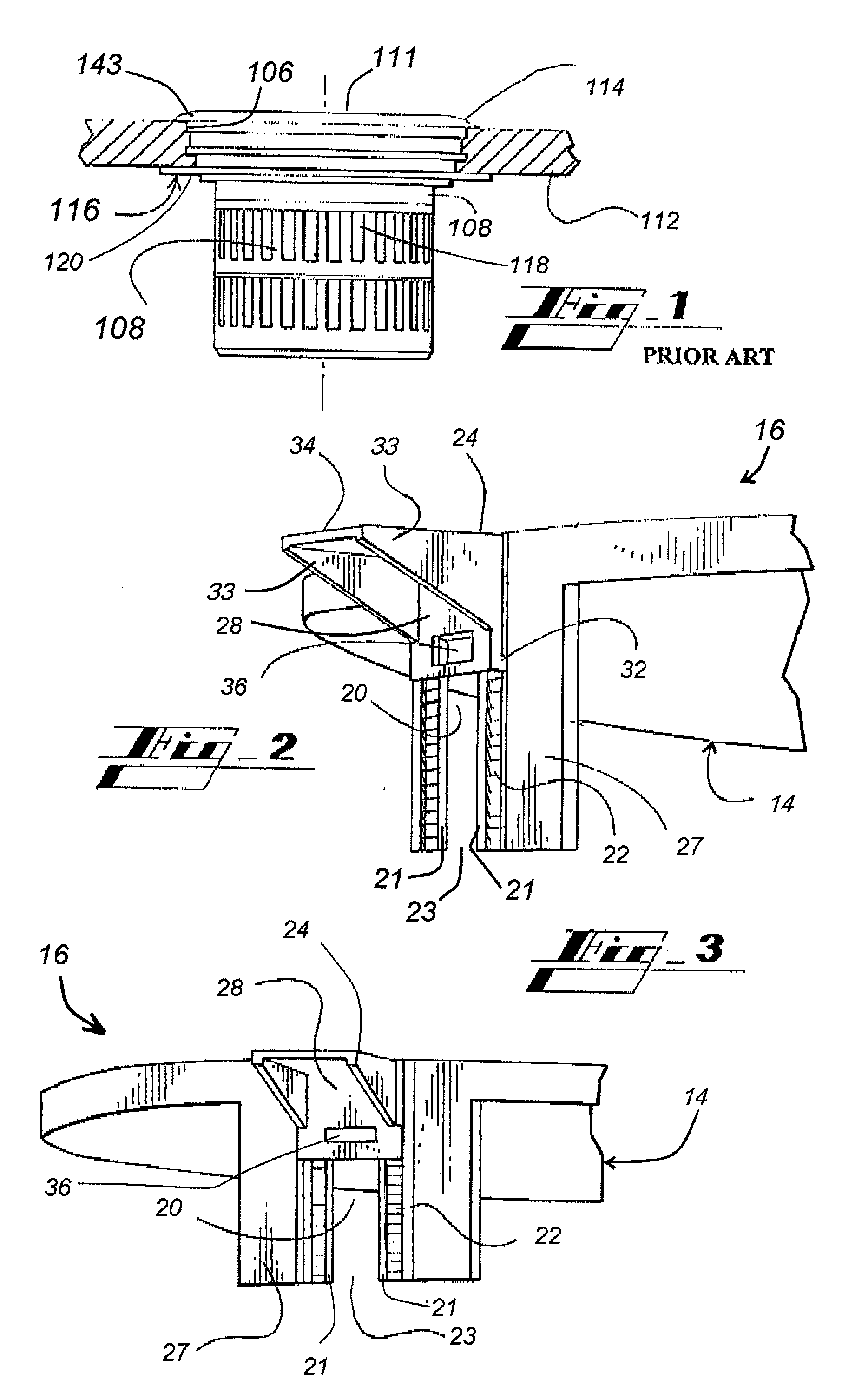
[0023]Turning to FIG. 1, a conventional basket type, air diffuser terminal 110 comprises a diffuser grille 111, a basket 108, and a mounting flange 116. Such a conventional air diffuser terminal 110 is mounted in an opening (or bore) 106 in a floor or other support structure 112 and is retained by the mounting flange 116. The mounting flange 116 comprises a trim ring 114 and a retaining ring 120 that respectively grip the upper and lower surfaces of the floor 112. The trim ring 114 has a lip 143 that bears against the top surface of the floor 112. The retaining ring 120 is threadingly engaged with the trim ring 114 to secure the air diffuser terminal 110 to the top and bottom surfaces of the floor 112. Particularly, the retaining ring 120 is rotated into engagement with the bottom of the floor 112 and the lip 143 engages the top surface of the floor 112. An air plenum below the floor 112 delivers heating and cooling air produced by the HVAC system to the air diffuser terminal 110. A...


PUM

PropertyMeasurementUnit
lengthaaaaaaaaaa
thicknessaaaaaaaaaa
angleaaaaaaaaaa

Abstract

A mounting flange for attaching an HVAC air diffuser terminal in an opening in a floor or other mounting surface. The mounting flange includes a trim ring and a flange clip. The flange clip is adjustably and movably received in a slot defined a side of the trim ring. A pawl on the flange clip engages with ratchets defined in a surface of the trim ring adjacent to the slot to maintain the flange clip in selected position relative the underside of a floor. The air diffuser terminal is secured in the floor opening between gripping surfaces on the flange clip and the trim ring. An optional screw operably connects the flange clip with the trim ring so that the diffuser may be securely tightened in the floor opening.

Description

CROSS REFERENCE TO RELATED APPLICATIONS[0001]This application claims the benefit of prior U.S. Provisional application Ser. No. 60 / 940,842, filed May 30, 2007.FIELD OF THE INVENTION[0002]The invention relates to air diffuser terminals utilized with HVAC distribution systems. More particularly, the invention relates to an improved mounting flange and method for installing an air diffuser terminal, especially in a floor opening. With greater particularity, the invention relates to a mounting flange with a ratchet and a pawl for securing the air diffuser terminal in a floor opening.BACKGROUND OF THE INVENTION[0003]Under floor HVAC systems carry conditioned air through a plenum located beneath the floor of an occupied space. The conditioned air flows into the occupied space via one or more air diffuser terminals mounted in openings in the floor. The air diffuser terminals are located at various positions in the floor to distribute the conditioned air evenly within the occupied space. In...

Claims


Application Information

Patent Timeline
Patent Type & Authority Applications(United States)
IPC IPC(8): F24F7/00B23P19/04
CPCF24F13/06Y10T29/53F24F2221/40F24F13/084
Inventor RIMMER, JULIAN
Owner PRICE
Why Eureka
Try Eureka