System and method for determining a transmit timing for communication in a radio communication system

a radio communication system and transmit timing technology, applied in the direction of transmission, synchronisation arrangement, wireless communication, etc., can solve the problems of inability to handle a relatively low load, lose uplink synchronization, and often have disadvantages, so as to achieve the effect of substantially reducing the signaling regarding synchronization procedures

Active Publication Date: 2009-12-24
HUAWEI TECH CO LTD
View PDF10 Cites 63 Cited by
  • Summary
  • Abstract
  • Description
  • Claims
  • Application Information

AI Technical Summary

Benefits of technology

[0014]Some embodiments as disclosed herein may provide advantages such as the user entity can perform a synchronization, or re-synchronization, without having to consume comm

Problems solved by technology

In addition, a UE that moves around in the radio network without using the uplink for a certain time will eventually lose its uplink synchronization due to changes in the relationship between the timing reference of the base station and the internal timing reference of the UE.
Such procedures, however, often have disadvantages.
For example, they can be contenti

Method used


Image

  • System and method for determining a transmit timing for communication in a radio communication system
  • System and method for determining a transmit timing for communication in a radio communication system
  • System and method for determining a transmit timing for communication in a radio communication system

Examples


Embodiment Construction

[0023]An embodiment of the present disclosure will now be described with reference to the 3rd Generation Partnership Program (3GPP) work on defining a future cellular communication system, which presently is called the Evolved Universal Terrestrial Radio Access (E-UTRA) or Long Term Evolution (LTE).

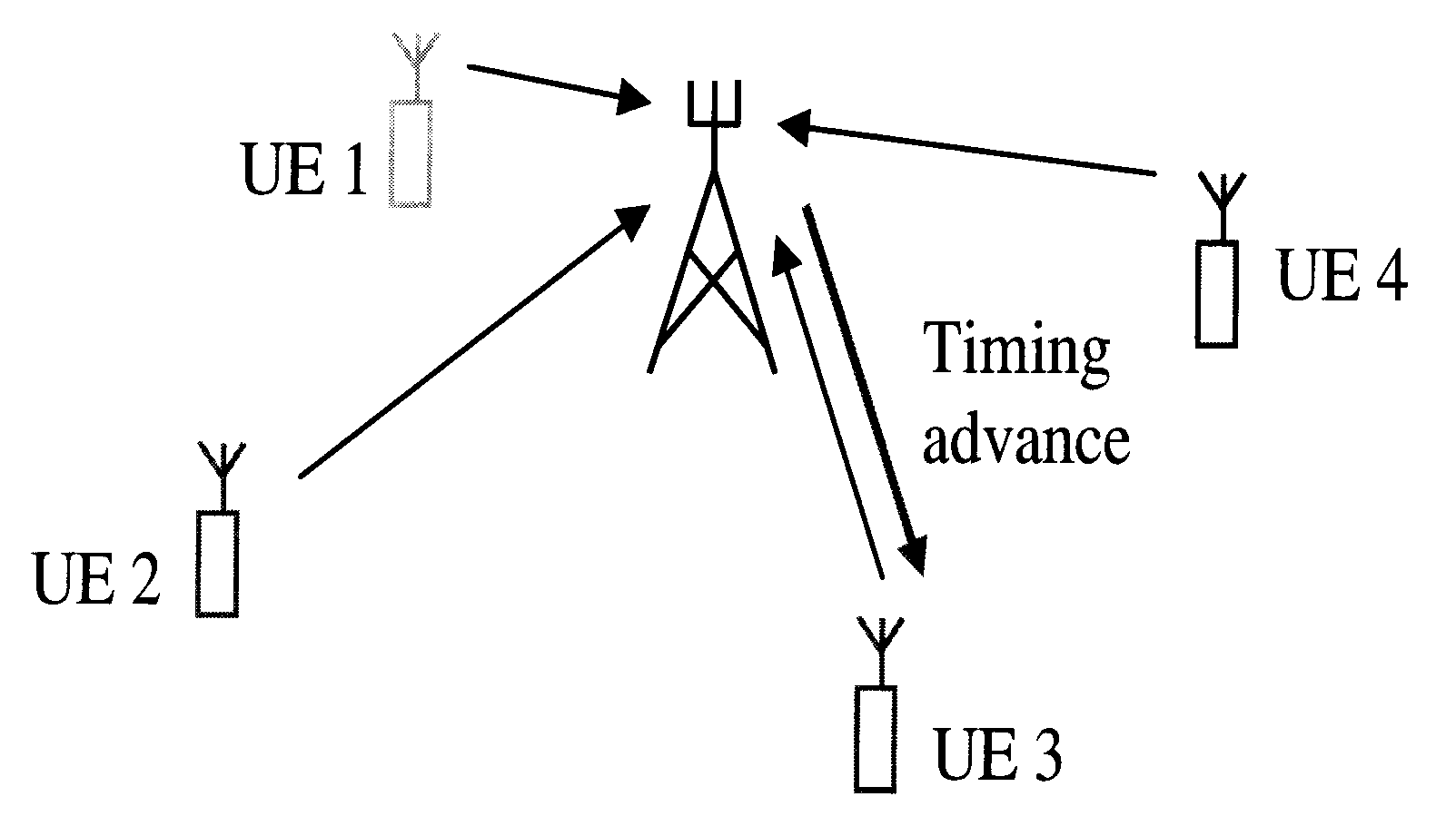
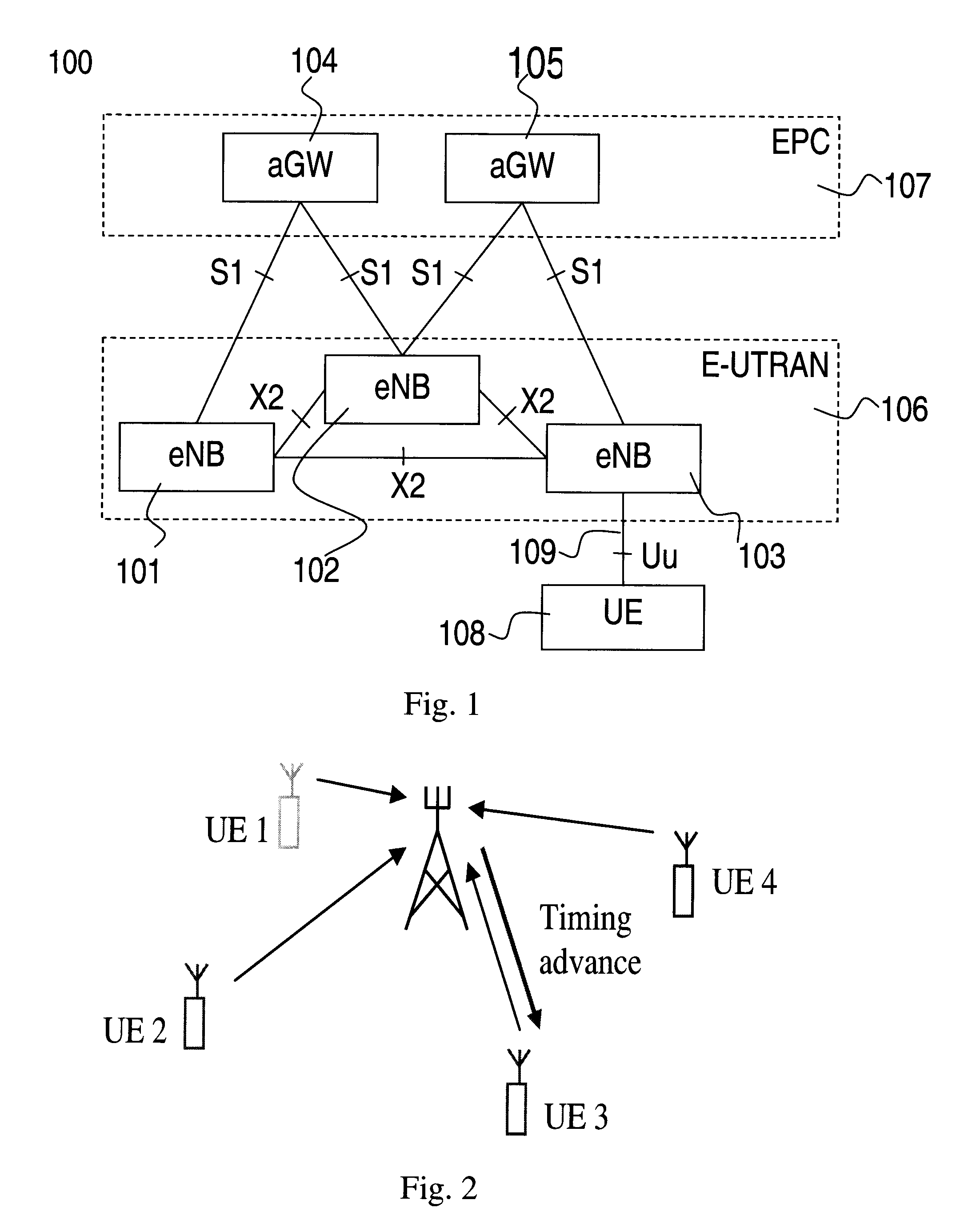
[0024]An example of the architecture of an E-UTRA system 100 is shown in FIG. 1, and consists of two kinds of nodes, radio base stations (stationary radio transceivers), eNBs (enhanced Node B) 101-103 and aGWs (access GateWay) 104-105, where the eNBs 101-103 belongs to the evolved UTRAN (E-UTRAN) 106 and the aGW belongs to the evolved packet core (EPC) 107. A user entity (UE) 108 connects to the network (E-UTRAN and EPC) by means of a radio interface, Uu interface 109. The eNB 101-103 handles communication over the radio interface in a certain coverage area, i.e., cell, which is the area wherein the radio signal is strong enough to allow a satisfactory communication with UEs within said a...


PUM


Abstract

A method for determining a transmission timing is provided. The method includes steps of, at a first point in time, determining a first transmission timing for transmissions from a user entity to a first radio transceiver, and determining a representation of a first position of the user entity in relation to the first radio transceiver and at least a second and a third radio transceiver. The method further includes, at a second point in time, subsequent to the first point in time, determining a representation of a second position of the user entity in relation to the first, second and third radio transceivers, and adjusting the transmission timing based on a difference of the first position and the second position.

Description

CROSS-REFERENCE TO RELATED APPLICATION[0001]This application is a continuation of PCT application No. PCT / CN2007 / 000629, filed on Feb. 28, 2007, titled “System and Method for determining a transmit timing for communication in a radio communication system,” the contents of which are incorporated herein by reference in its entirety.TECHNICAL FIELD[0002]The present disclosure relates to a method for determining a transmit timing in a radio communication system.BACKGROUND[0003]Wireless mobile radio communication systems are usually cellular, i.e., the total coverage area of such systems is divided into smaller areas wherein each of these smaller areas is associated with a radio base station having one or more radio transceivers for providing communication resources via a radio interface for communication with User Entities (UE), such as mobile phones, smart phones or handheld computers having communication capabilities, located in said area. These areas are usually called cells.[0004]Su...

Claims


Application Information

Patent Timeline
IPC IPC(8): H04B7/005H04W4/02
CPCH04W56/0045H04W4/02
Inventor SANDBERG, DAVID
Owner HUAWEI TECH CO LTD
Why Eureka
Try Eureka