Thermopile IR detector package structure

Inactive Publication Date: 2005-04-21
FORMOSA NANOMEMS TECH
View PDF4 Cites 53 Cited by
  • Summary
  • Abstract
  • Description
  • Claims
  • Application Information

AI Technical Summary

Benefits of technology

[0008] Another object of the present invention is to provide a thermopile IR detector package structure, which can match a substrate to form a surface mount device (SMD) for facilitating mass production and reducing the fabrication procedures, material, volume and weight.
[0009] Yet another object of the present invention is to provide a thermopile IR detector package s

Problems solved by technology

However, the thermoelectric voltage provided by a single thermocouple is much limited.
However, this kind of metal transistor package has a complicated fabrication process, a large size and a high cost.
Moreover, during the fabrication of printed cir

Method used


Image

  • Thermopile IR detector package structure
  • Thermopile IR detector package structure
  • Thermopile IR detector package structure

Examples


Embodiment Construction

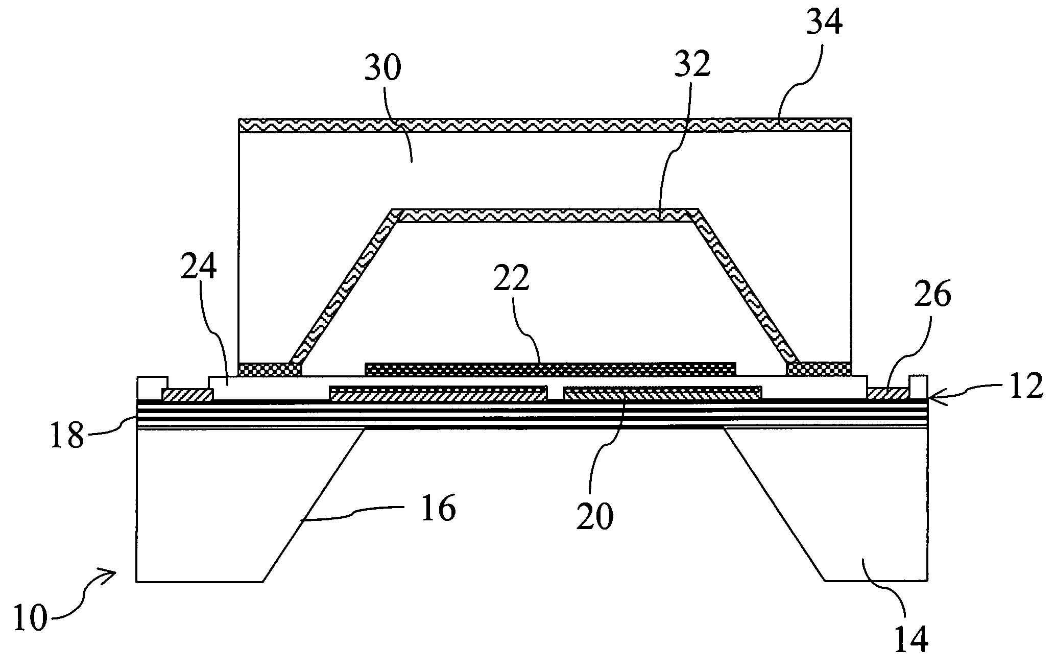
[0020] The present invention provides a new thermopile IR detector package structure, which makes use of an encapsulation formed by the silicon micro-electro-mechanical technique to seal a detector, and a carrier substrate is matched to form an SMD for facilitating mass production and reducing the fabrication procedures, material, volume and weight. The conventional TO-5 or TO-18 package can thus be replaced.

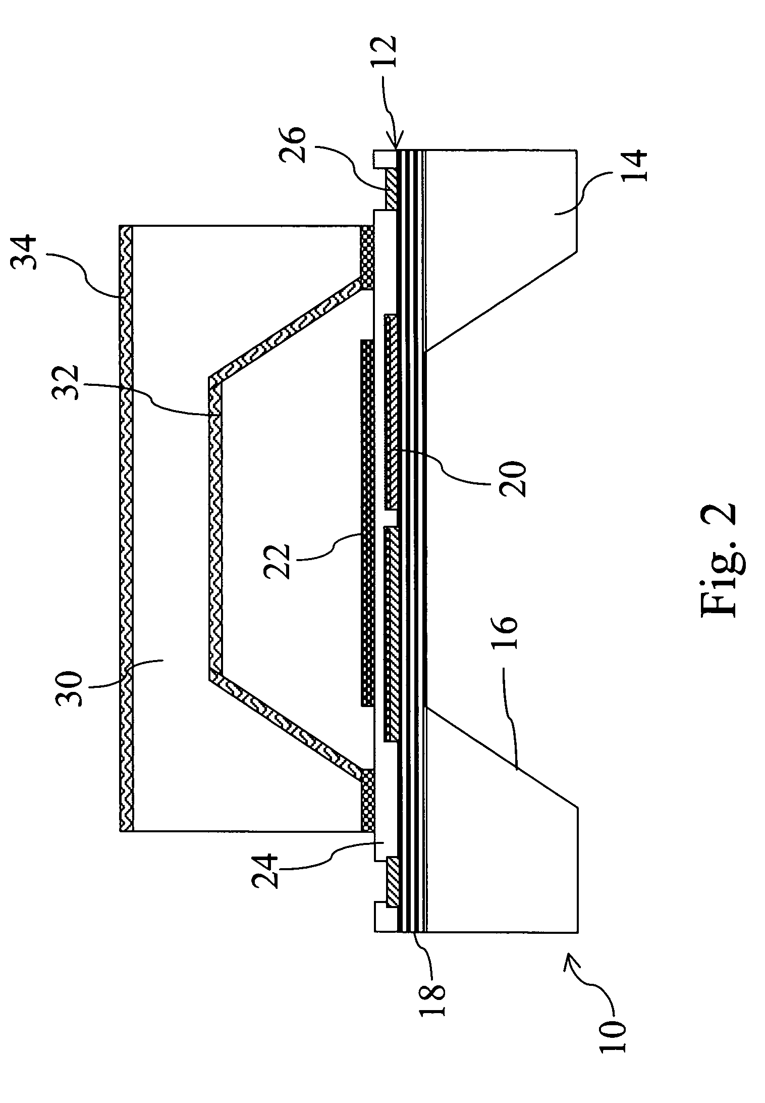
[0021] As shown in FIG. 2, the package structure of a thermopile IR detector 10 comprises a thermopile detector 12 and an encapsulation 30. The detector 12 includes a single-silicon substrate 14. A cavity portion 16 is etched in the substrate 14 through chemical etching. A thin-film float board 18 covers over the cavity portion 16. The thin-film float board 18 is composed of more than one layer of insulating films, preferred to be silicon oxide and silicon nitride. One or a plurality of thermoelectric components 20 are then arranged on the thin-film float board 18. These thermo...


PUM


Abstract

A thermopile IR detector package structure makes use of the silicon micro-electro-mechanical processing technique fabricate an encapsulation having a cavity. The encapsulation is then installed onto a substrate of a detector to seal thermoelectric components on the substrate. In addition to having the sealing function, the encapsulation also has the function of detecting the spectrum and field of view. Next, a carrier substrate is combined with sensing components to form a surface mount device applicable to assembly and fabrication of various related circuits. The thermopile IR detector package structure not only facilitates mass production and reduces fabrication process, material, volume ad weight, but the formed surface mount device is also in agreement with automatically produced electronic components.

Description

FIELD OF THE INVENTION [0001] The present invention relates to a thermopile IR detector package structure and, more particularly, to a technique making use of the silicon micro-electro-mechanical processing technique to fabricate devices and encapsulations. This kind of package structure can fabricate thermopile IR detection surface mount devices to match automatic production trend of the surface mount technology (SMT). BACKGROUND OF THE INVENTION [0002] Using a thermocouple for temperature measurement is a well-known technique. When two different kinds of metals (conductors) make up a loop, a voltage will be generated if the temperatures of two joints are different. This thermoelectric characteristic is called the Seebeck effect. The temperature difference of two ends of a thermocouple can be known by measuring the magnitude of the Seebeck voltage. [0003] Through a special structure design, a thermocouple can be used for thermal radiation measurement by the temperature difference o...

Claims


Application Information

Patent Timeline
IPC IPC(8): G01K7/04H01L31/0203H01L35/28
CPCG01K7/04H01L27/14618H01L31/0203H01L2924/15311H01L2224/48091H01L2924/00014
Inventor LAN, ALEX H.WENG, PING-KUO
Owner FORMOSA NANOMEMS TECH
Why Eureka
Try Eureka