
Broadband low cross-polarization printed dipole antenna with parasitic element

A dipole antenna and parasitic element technology, which is applied to antennas, devices that make the antennas work in different frequency bands at the same time, electrical components, etc. performance effect

Inactive Publication Date: 2012-05-02
UNIV OF ELECTRONICS SCI & TECH OF CHINA
View PDF4 Cites 64 Cited by
  • Summary
  • Abstract
  • Description
  • Claims
  • Application Information

AI Technical Summary

Problems solved by technology

However, the size of the antenna is very large, and the distance between the parasitic unit and the dipole is about 1 / 4 wavelength, which is extremely inconvenient in practical applications
In the article "Equivalent-Circuit Analysis of a Broadband Printed Dipole With Adjusted Integrated Balun and an Array for Base Station Applications" (IEEE Transactions on antennas and propagation, 2009), RongLin Li et al. The position of the feed point of the integrated balun of the sub-antenna has been adjusted, from the upper feed of the dipole slot to the lower feed to facilitate the realization of dual polarization. At the same time, the impedance bandwidth of the antenna remains unchanged, but the relative The bandwidth is narrower, only 40%

Method used


Image

  • Broadband low cross-polarization printed dipole antenna with parasitic element
  • Broadband low cross-polarization printed dipole antenna with parasitic element
  • Broadband low cross-polarization printed dipole antenna with parasitic element

Examples


Embodiment Construction

[0018] specific implementation plan

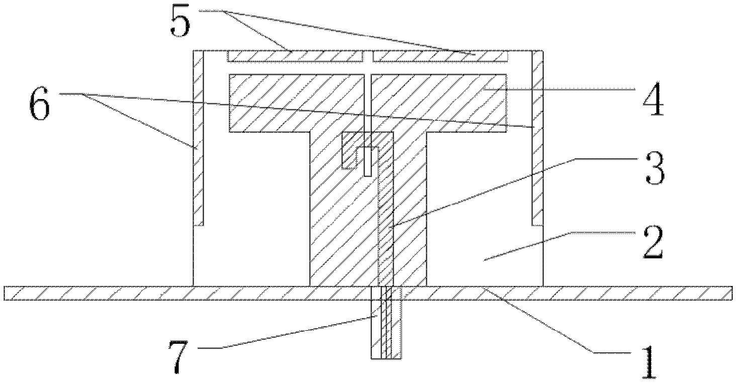
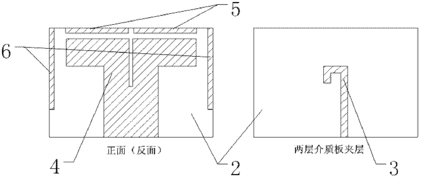
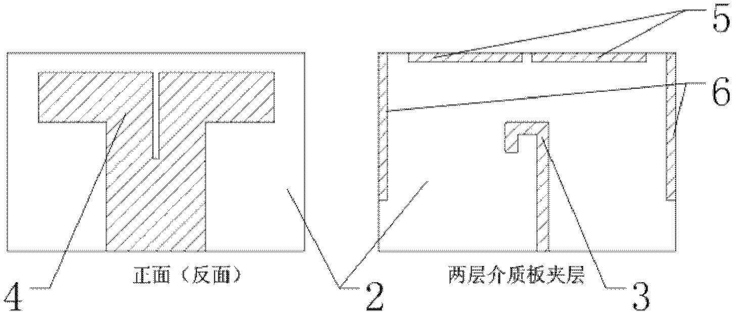
[0019] figure 1 with figure 2 An exemplary design device for a broadband low cross-polarization printed dipole antenna with parasitic elements is described. According to the illustration, the device mainly includes metal reflector 1, two-layer dielectric board 2, stripline feed integrated balun 3, two-layer main radiation patch (dipole arm) 4, and four upper ends of dipole arm. One parasitic unit 5, four parasitic units 6 on both sides of the dipole arm and SMA connector 7. The metal reflector 1 is made of a 3mm thick aluminum plate with a size of 10cm*10cm, and a circular hole with a diameter of 4.1mm is drilled in the middle of the reflector. The two layers of dielectric boards 2 are both made of dielectric boards with a thickness of 0.7874 mm and a relative dielectric constant of 2.2, and the two layers of dielectric boards are glued together. The stripline integrated balun 3 adopts a Γ-shaped balun with a width of 2mm and is print...


PUM


Abstract

The invention discloses a broadband low cross-polarization printed dipole antenna with a parasitic element. The antenna has the advantages of broad frequency band, low cross-polarization, stable directional diagram, small size and simple structure. The antenna adopts a double-layer printed dipole way, and meanwhile, rectangular patches are uploaded on the upper end and at two sides of a dipole arm. The broadband low cross-polarization printed dipole antenna has the basic structure as follows: a metal earth plate, two layers of dielectric slabs, strip line feeding balun, a double-layer printed dipole arm, a rectangular patch arranged on the upper end of the dipole arm, rectangular patches arranged at two sides of the dipole arm and an SMA (Small A Type) joint. The greatest innovation of the broadband low cross-polarization printed dipole antenna is that the ultra broadband character and stable directional diagram character are obtained through uploading the parasitic elements in the manner of the rectangular patches on the upper end and at two sides of the double-layer printed dipole arm, 75% of bandwidth can be achieved under the condition that the standing-wave ratio is smaller than 1.5, and meanwhile, the broadband low cross-polarization printed dipole antenna has a stable directional diagram in the bandwidth, low cross-polarization and grain up to 6.1-9.3dBi. The size of the antenna is reasonably changed, i.e., other concrete embodiments of the invention can be formed.

Description

technical field [0001] The invention belongs to the technical field of antenna engineering, and relates to a printed dipole antenna, in particular to a double-layer printed dipole antenna with broadband and low cross polarization that can be used for wireless communication and phased array radar. Background technique [0002] Printed dipole antennas have the advantages of small size, light weight, simple structure, easy integration, and easy mass production, and are widely used in communications and radar. But it also has disadvantages such as narrow bandwidth and high cross polarization. In some applications, in order to improve the performance of the system, it is required that the antenna has broadband and low cross-polarization characteristics. For example, in a base station antenna, the antenna bandwidth needs to be increased in order to increase the data transmission rate. In a dual-polarized base station antenna, in order to ensure high polarization isolation, the a...

Claims


Application Information

Patent Timeline
Patent Type & Authority Applications(China)
IPC IPC(8): H01Q1/38H01Q5/01H01Q19/10H01Q5/10
Inventor 杨仕文朱全江龚雪郑丽罗伟熊伟聂在平
Owner UNIV OF ELECTRONICS SCI & TECH OF CHINA
Learn More