A LED display screen display calibration system and calibration method

A technology of LED display and display calibration, applied to static indicators, cathode ray tube indicators, instruments, etc., can solve the problems of inconvenient mass production, calibration disorder, troublesome maintenance and operation, etc., to facilitate mass production and reduce bandwidth requirements , The effect of simple maintenance operation

Active Publication Date: 2008-07-09
SHENZHEN AOTO ELECTRONICS
View PDF0 Cites 67 Cited by
  • Summary
  • Abstract
  • Description
  • Claims
  • Application Information

AI Technical Summary

Problems solved by technology

[0014] 1. Since the mass production and inventory of LED displays are based on the display module as the basic unit, the above-mentioned brightness and chromaticity calibration method is adopted, and the calibration files are stored in the sending card or receiving card. It is required that the modules that make up the screen or cabinet must be Arrange them in a certain order, and the disordered order will cause the correction disorder. Therefore, the strict requirements on the order of the modules in the screen or cabinet are not convenient for mass production;
[0015] 2. Since the order of the display modules may be random after each production, when the display modules are combined into a screen or cabinet, the calibration files must be reorganized according to the new order and downloaded to the sending card or receiving card through the communication line. It is stored in the card, so the display module cannot complete the calibration synchronously when the generation is completed, and the synchronization of the calibration is poor
[0016] 3. For the installed LED display, when a module is damaged and needs to be replaced, it is necessary to call out the calibration file of the module according to the serial number of the new module, and then download it to the sending card or Stored in the receiving card, the maintenance operation is extremely troublesome

Method used


Image

  • A LED display screen display calibration system and calibration method
  • A LED display screen display calibration system and calibration method
  • A LED display screen display calibration system and calibration method

Examples


Embodiment Construction

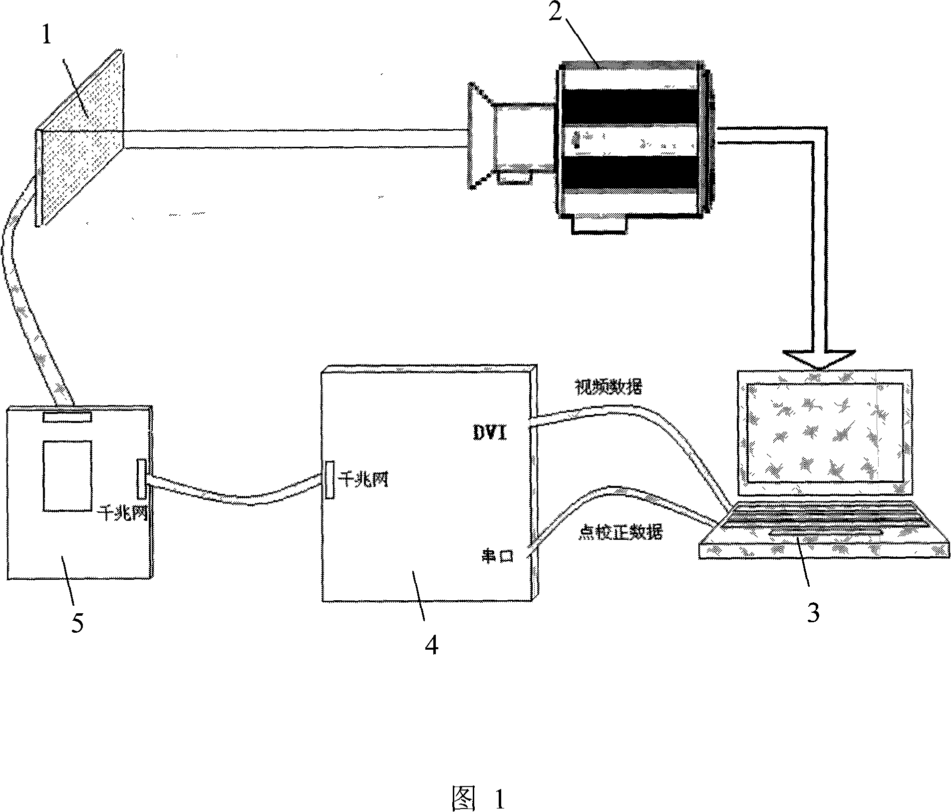
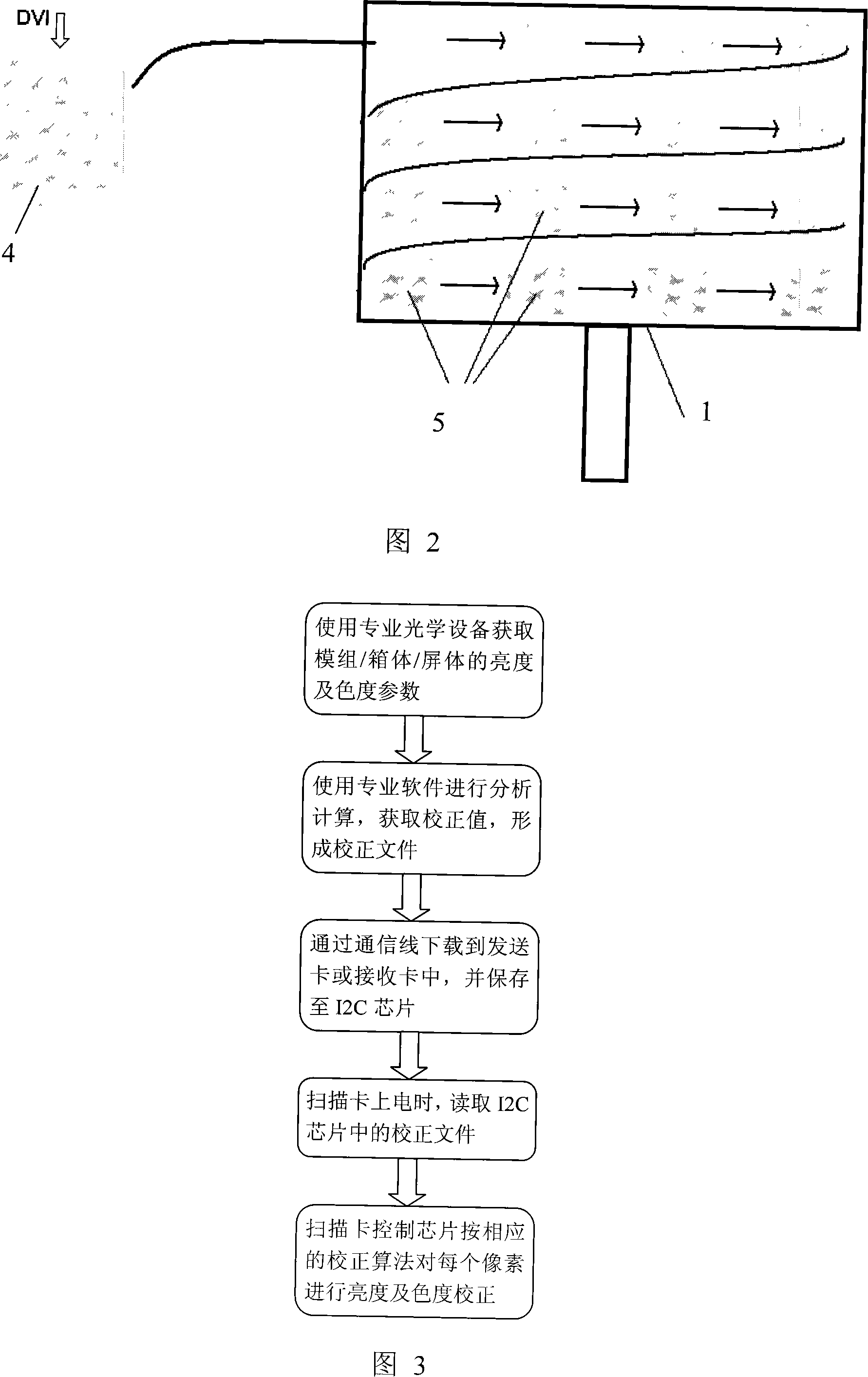
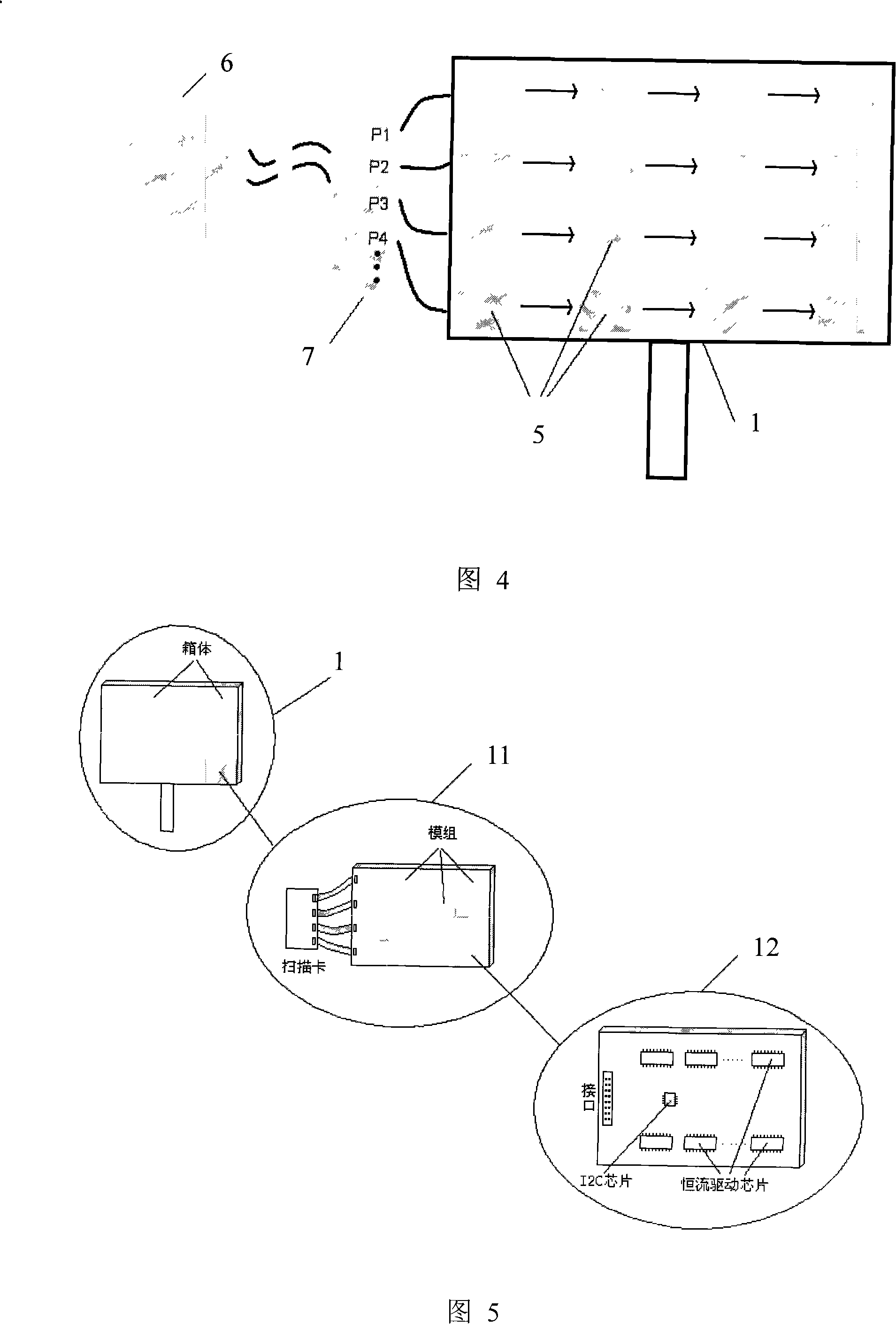
[0051] As shown in FIG. 4 and FIG. 5 , the LED display display correction system of the present invention includes a video acquisition controller 6 , a data distributor 7 , a scan control card 5 and an LED display module 12 .

[0052] Wherein, the video acquisition controller 6 includes a large-scale editable logic array chip connected through a corresponding bus, a DVI image receiving circuit, a Gigabit network communication interface circuit, an optical fiber communication interface circuit, a general serial communication interface and a high-speed memory circuit.

[0053] The data distributor includes a large-scale programmable logic array chip, a Gigabit network communication interface circuit, an optical fiber communication interface circuit and an environment monitoring circuit.

[0054] As shown in Figure 9, the scan control card 5 includes an editable logic array chip (FPGA) 52, a gigabit network communication interface circuit 51, a memory circuit 54, a DC-DC power sup...


PUM


Abstract

The invention relates to a display calibration system of a LED display screen and a calibration method thereof. The system comprises a video capture controller, a data distributor, scanning control cards and LED display modules; the memory chips of the display modules save simple-point calibration data of the display modules, which is uniformly arrayed in a LED display box in the light of a row or column cascade; a plurality of LED display boxes are uniformly arrayed in the light of the row or column cascade to constitute the LED display screen; the head end scanning control cards of each row cascade or each column cascade of the LED display screen are respectively connected with a GigE communication interface circuit of the data distributor, and the data distributor is connected with the GigE communication interface circuit of the video capture controller via the GigE communication interface circuit thereof; based on the systems, the method takes the LED display modules for saving the simple-point calibration data as units, thus realizing the calibration of display screen pixel. The invention reduces the bandwidth requirements on the connection among the scanning control cards, realizes the function of plug and play of the display modules, is convenient for batch production and simple in maintenance operation, and improves the synchronicity of calibration of the display screen.

Description

technical field [0001] The present invention relates to a display correction system, and also relates to a correction method of the display correction system, more specifically, to an LED display display correction system and a correction method. Background technique [0002] With the mass application of various public information media, people can choose different display media to carry information, such as neon lights, printed advertising boards, three-sided flip advertising boards, PDP TV walls, etc. However, the above-mentioned display media all have defects such as limited display content or unsatisfactory brightness and effect. With the continuous improvement of user requirements for the performance of display devices for large-screen display media indoors and outdoors in terms of color, brightness, video effects, reliability, and lifespan, the display system is required to display true-color images that are close to natural colors, and It has a high display brightnes...

Claims


Application Information

Patent Timeline
Patent Type & Authority Applications(China)
IPC IPC(8): G09G3/32G09G5/36G09G5/00G09G5/02G09G5/10
Inventor 吴振志王昊翔吴涵渠卓元元
Owner SHENZHEN AOTO ELECTRONICS
Why Eureka
Try Eureka