Column Installed Condenser

a condenser and column technology, applied in the field of heat exchangers, can solve the problem of significant vertical space taken by such exchangers

Active Publication Date: 2009-12-31
UOP LLC
View PDF14 Cites 9 Cited by
  • Summary
  • Abstract
  • Description
  • Claims
  • Application Information

AI Technical Summary

Problems solved by technology

However, the vertical space taken by such exchangers is significant.

Method used


Image

  • Column Installed Condenser
  • Column Installed Condenser
  • Column Installed Condenser

Examples


Embodiment Construction

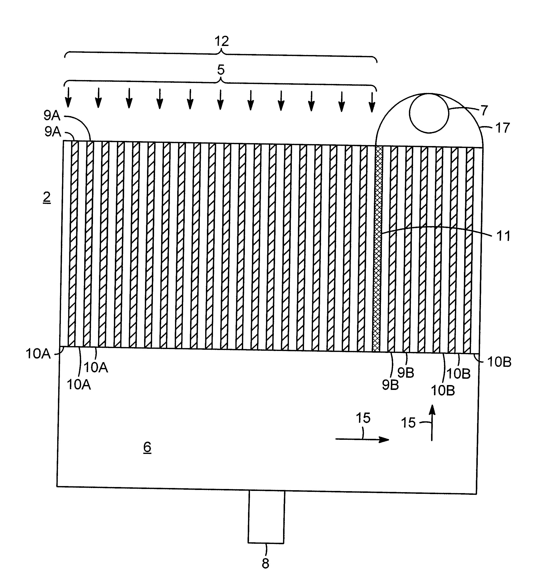
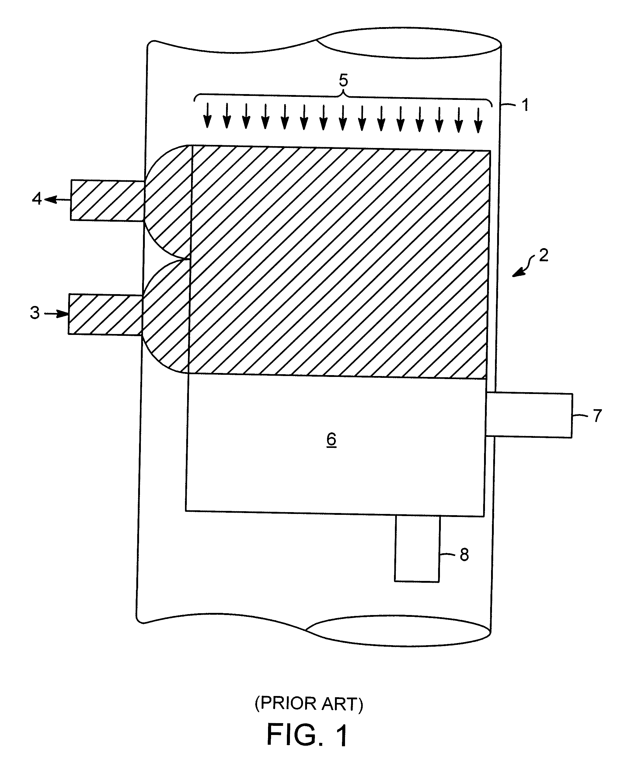
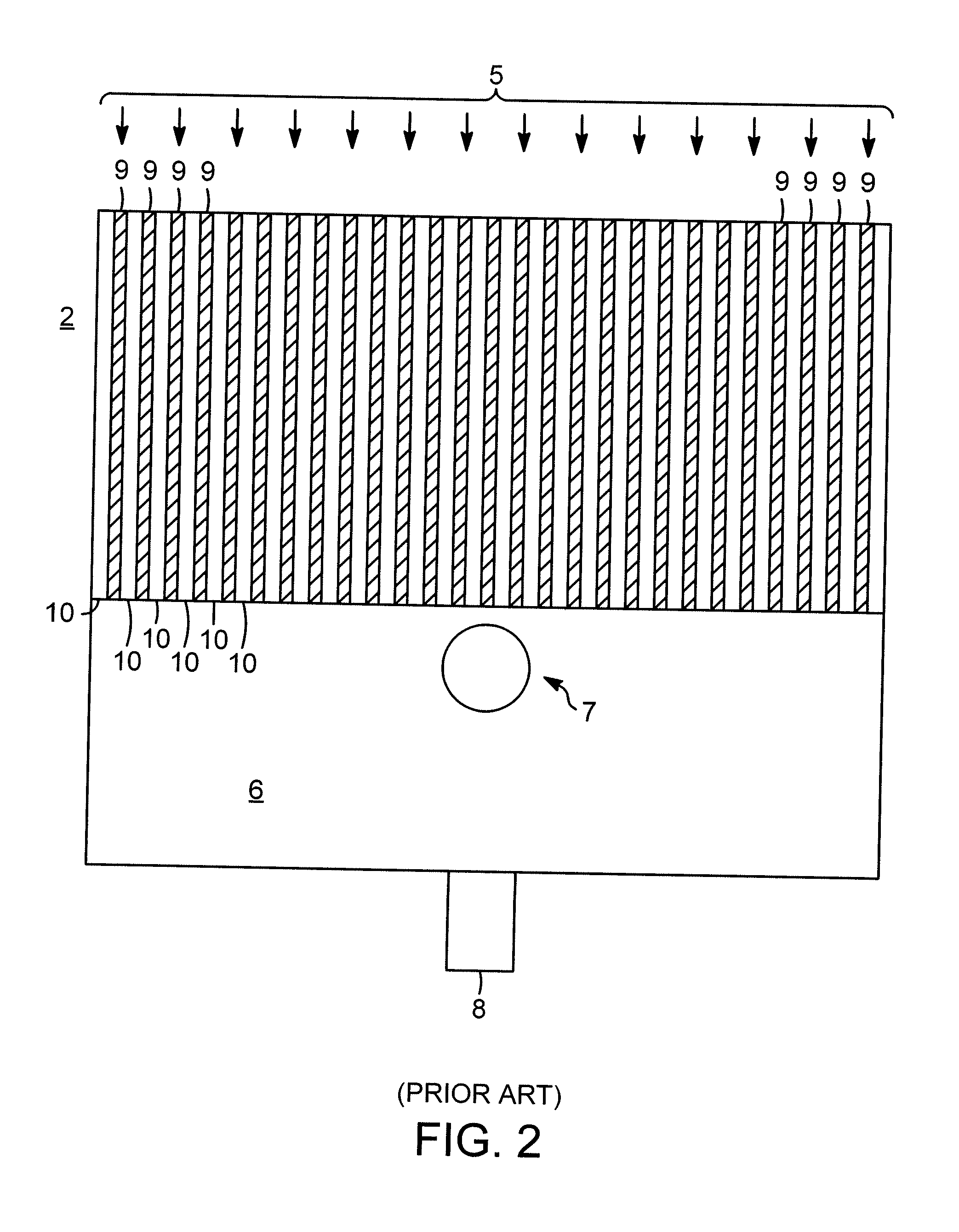
[0023]Vertical plate heat exchangers are used in reactor vessels and in separation or fractionation columns to withdraw heat from the materials flowing therein. Typically, a liquid condensate stream is recovered and a stream of non-condensable materials, that is, compounds that do not condense at the conditions of operation of the heat exchanger, are separately recovered. Such heat exchangers are known to the skilled practitioner.

[0024]For simplicity and ease of description, embodiments of the invention will be described with particularity as they relate to separation or fractionation columns, or, simply, columns. However, many of these embodiments will be readily applicable to reactor vessels and other vessels from which heat is to be removed.

[0025]Further, as used herein, the word “product” in relation to a stream does not indicate that the stream is a desired product or a material sought to be recovered from the process. Similarly, non-condensables, as that word is defined above,...


PUM

PropertyMeasurementUnit
areaaaaaaaaaaa
volumeaaaaaaaaaa
heat exchange areaaaaaaaaaaa

Abstract

A reactor-installed or column-installed vertical plate heat exchanger having channels for flow of cooling fluid and vertical passageways between the cooling fluid channels for flow of product. A divider is located between a first fraction and a second fraction of the product vertical passageways and a vapor product inlet communicates with the tops of the product vertical passageways in the first fraction. A product collection volume communicates with the bottoms of the product vertical passageways and an outlet communicates with the product collection volume for recovering condensed product. An uncondensed vapor outlet communicates with the tops of the vertical passageways in the second fraction for removing uncondensed vapor from the heat exchanger.

Description

CROSS-REFERENCE TO RELATED APPLICATION[0001]This application claims priority to Provisional U.S. Application No. 61 / 077,000, filed Jun. 30, 2008, all of which is incorporated by reference.FIELD OF THE INVENTION[0002]This invention relates to heat exchangers installed within other vessels. In particular, the invention relates to plate-type heat exchangers, and more particularly to such an exchanger installed as a condenser in a reactor or a separation or fractionation column.DESCRIPTION OF RELATED ART[0003]Many industries such as petrochemical, chemical and petroleum refining use columns for separating mixtures. Such columns are typically cylindrical, vertically orientated vessels wherein rising vapor and descending liquid come into contact, transfer components, separate, and pass respectively towards the top and bottom sections of the column. Frequently, columns contain vapor-liquid contacting devices to enhance the contacting and separation of the vapor and liquid phases. Examples ...

Claims


Application Information

Patent Timeline
Patent Type & Authority Applications(United States)
IPC IPC(8): F28B3/00F28F3/00
CPCB01D5/0012B01D5/0015B01D5/006B01D5/0063F25J5/005F25J2250/10F25J2250/20F25J2290/32F28D9/0006F25J2250/02
Inventor DALY, PHILLIP F.
Owner UOP LLC
Why Eureka
Try Eureka