Power tool

Inactive Publication Date: 2009-12-31
MAKITA CORP
View PDF27 Cites 50 Cited by
  • Summary
  • Abstract
  • Description
  • Claims
  • Application Information

AI Technical Summary

Benefits of technology

[0006]Accordingly, it is an object of the present invention to provide a technique wh

Problems solved by technology

Therefore, if an attempt is made to obtain a desired vibration proofing effect by causing the direction of deformation of the elastic element to be closer to the axial direction of the hammer bit, the distance between the piv

Method used


Image

  • Power tool
  • Power tool
  • Power tool

Examples


Example

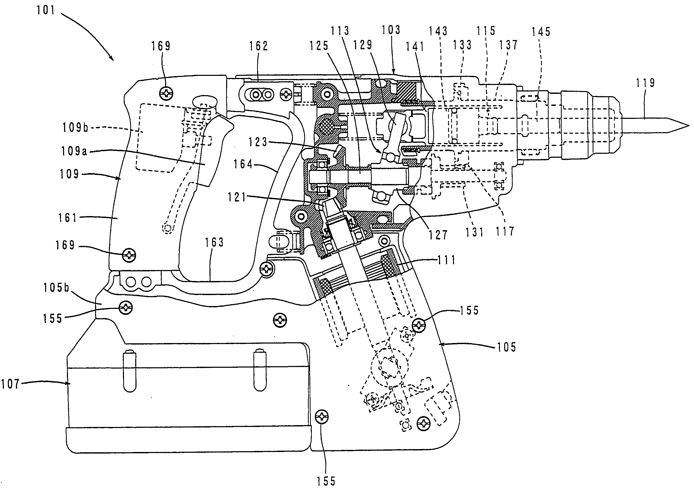
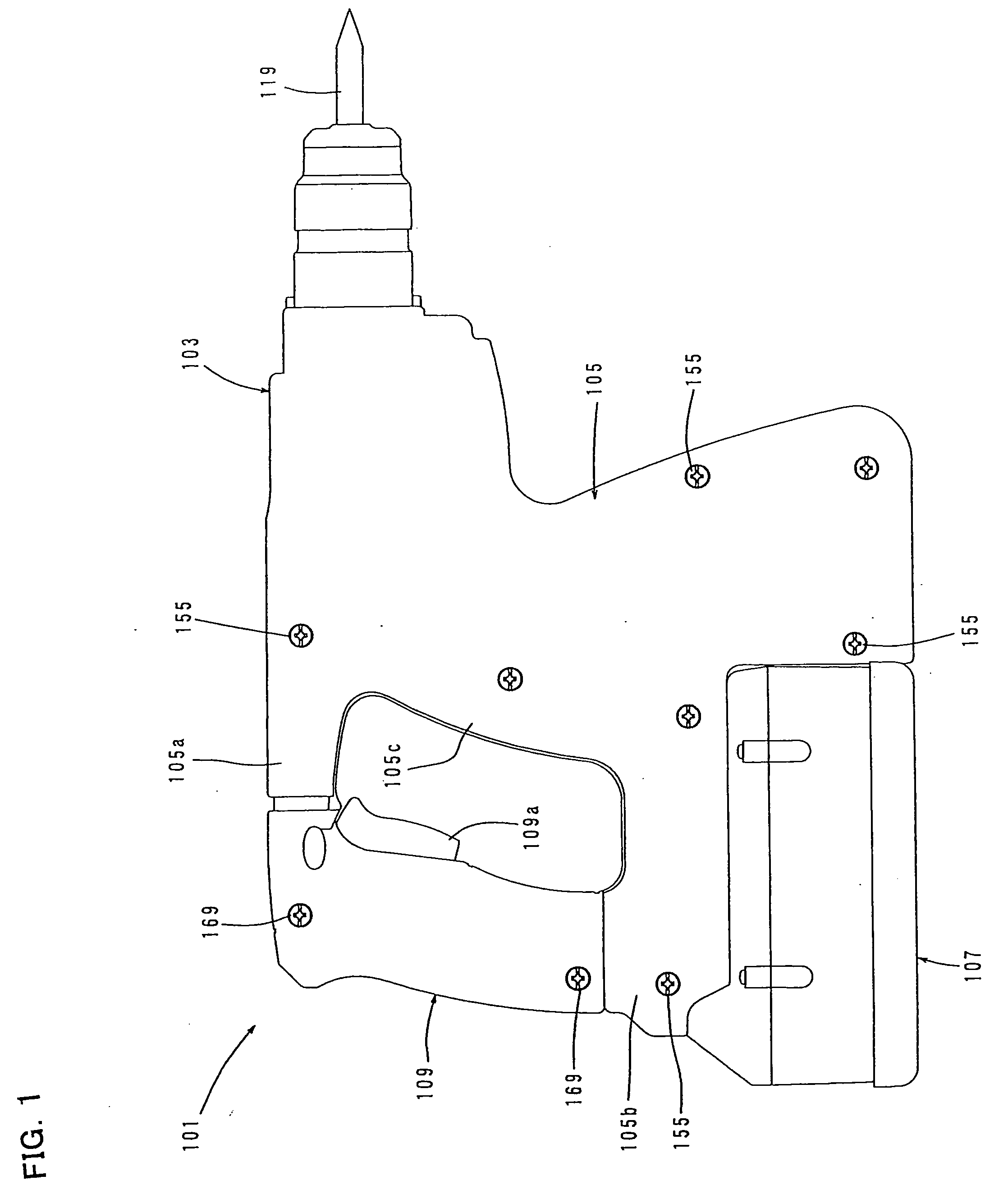
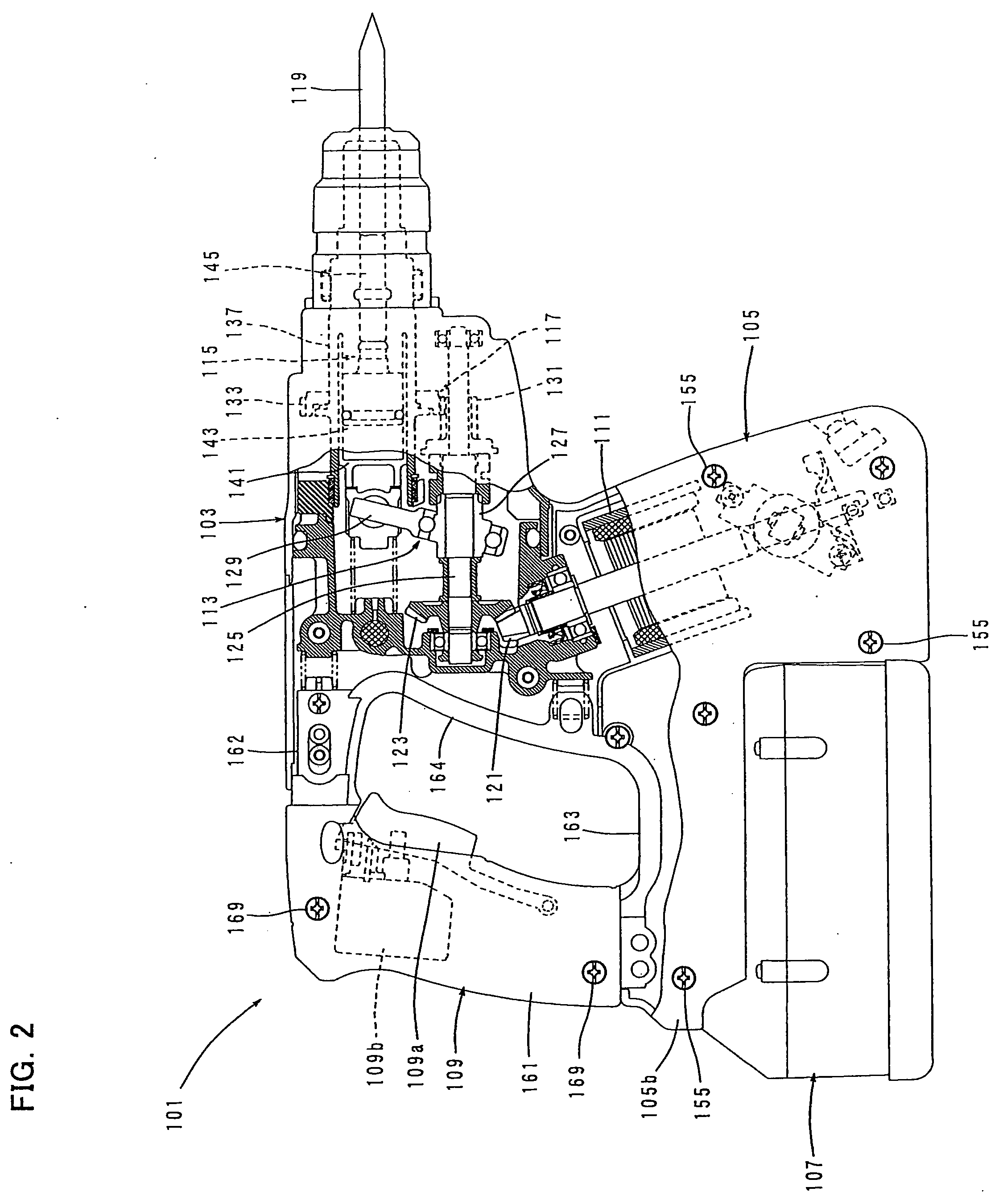
[0030]Each of the additional features and method steps disclosed above and below may be utilized separately or in conjunction with other features and method steps to provide and manufacture improved power tools and method for using such power tools and devices utilized therein. Representative examples of the present invention, which examples utilized many of these additional features and method steps in conjunction, will now be described in detail with reference to the drawings. This detailed description is merely intended to teach a person skilled in the art further details for practicing preferred aspects of the present teachings and is not intended to limit the scope of the invention. Only the claims define the scope of the claimed invention. Therefore, combinations of features and steps disclosed within the following detailed description may not be necessary to practice the invention in the broadest sense, and are instead taught merely to particularly describe some representativ...


PUM


Abstract

It is an object of the invention to provide a technique which contributes to reduced size of a vibration-proof handle for a hand-held power tool. A representative hand-held power tool includes a power tool body 103 having a tip end region to which a tool bit 119 can be coupled, and a handle 109 arranged on the rear of the power tool body 103 on the side opposite to the tool bit 119 and designed to be held by a user. The handle 109 is connected to the power tool body 103 via elastic elements 181, 183 and can slide with respect to the power tool body 103 in an axial direction of the tool bit 119. The power tool body 103 has an extending region 105b that extends to a lower region of the handle 109 and receives the sliding movement of the handle 109.

Description

BACKGROUND OF THE INVENTION[0001]1. Field of the Invention[0002]The present invention relates to a vibration-proof handle of a hand-held power tool such as a hammer and a hammer drill.[0003]2. Description of the Related Art[0004]A hand-held electric hammer having a vibration-proof handle is disclosed, for example, in Japanese non-examined laid-open Patent Publication No. 2005-219195. In this electric hammer, the vibration-proof handle to be held by a user during hammering operation is mounted to a hammer body via an elastic element for vibration absorption. More specifically, in the vibration-proof handle, one (lower) end of a grip part in its longitudinal direction is mounted to the rear of the hammer body such that it can rotate with respect to the hammer body on a pivot in the axial direction of the tool bit, and the other (upper) end is connected to the rear of the hammer body via the elastic element.[0005]In the above-described rotary vibration-proofhandle which is supported vi...

Claims


Application Information

Patent Timeline
IPC IPC(8): B25D17/04B25D17/24
CPCB25D17/043B25D2211/003B25F5/02B25D2250/121B25F5/006B25D2211/061
Inventor FURUSAWA, MASANORIKASUYA, YOSHIHIRO
Owner MAKITA CORP
Why Eureka
Try Eureka