Aircraft noise reduction apparatus

a technology for reducing aircraft noise and equipment, which is applied in the direction of aircraft control, aircraft components, aircraft gear, etc., can solve the problems of increasing the time it takes for ground crews to deal with aircraft, creating dominant noise, and increasing the noise of aircraft, so as to facilitate access to noise inducing elements, reduce aircraft noise, and facilitate access

Inactive Publication Date: 2009-12-31
AIRBUS OPERATIONS LTD
View PDF17 Cites 21 Cited by
  • Summary
  • Abstract
  • Description
  • Claims
  • Application Information

AI Technical Summary

Benefits of technology

[0006]Preferably the noise reduction apparatus includes attachments suitable for fixing it to the landing gear. The apparatus may be arranged such that when the landing gear is unloaded the noise reduction attachment is in the first position. The landing gear is unloaded when the aircraft is in the air and the landing gear is fully extended. This position may also be known as the “weight off wheels” position. The apparatus may be arranged such that when the landing gear is loaded the noise reduction attachment is in the second position. The landing gear is in the loaded position when the aircraft is on the ground and the landing gear is compressed by the weight of the aircraft. This position may also be known as the “weight on wheels” position. The movement of the noise reduction attachment may be dependent on the load on the landing gear. Therefore, in this embodiment of the invention, when the aircraft is landing or has left the ground when taking off, the noise reduction attachment is in the first position and deflects air away from the noise inducing component of the landing gear. When the aircraft is on the ground, the noise reduction attachment apparatus is in the second position and allows the ground crew access to the noise inducing component without them having to undertake any additional work.
[0007]The noise reducing attachment may comprise a first fairing part and a second fairing part so arranged that in the first position the first and second fairing parts act together as a fairing, whereas in the second position the second fairing part is moved to a position which facilitates access to the noise inducing element. The first fairing part may include an aperture to facilitate such access, the aperture being screened by the second fairing part when in the first position.
[0008]The invention also provides a method of reducing aircraft noise, wherein the method comprises the steps of: providing an aircraft landing gear with a noise reducing fairing associated with a noise inducing component; and a part of the landing gear moving the noise reducing attachment between a first, noise reducing, position and a second, access, position.

Problems solved by technology

The dominant noise created by some aircraft when landing, as perceived at ground level, is starting to become the airframe noise.
However, this increases the time it takes for a ground crew to deal with an aircraft and introduces the risk that the fairing is not properly secured to the aircraft prior to the aircraft taking off.

Method used


Image

  • Aircraft noise reduction apparatus
  • Aircraft noise reduction apparatus
  • Aircraft noise reduction apparatus

Examples


Embodiment Construction

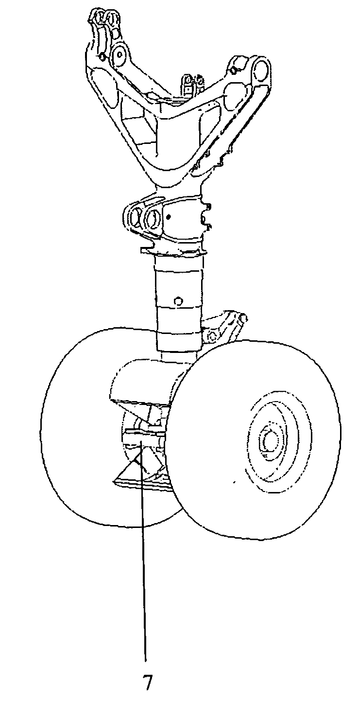
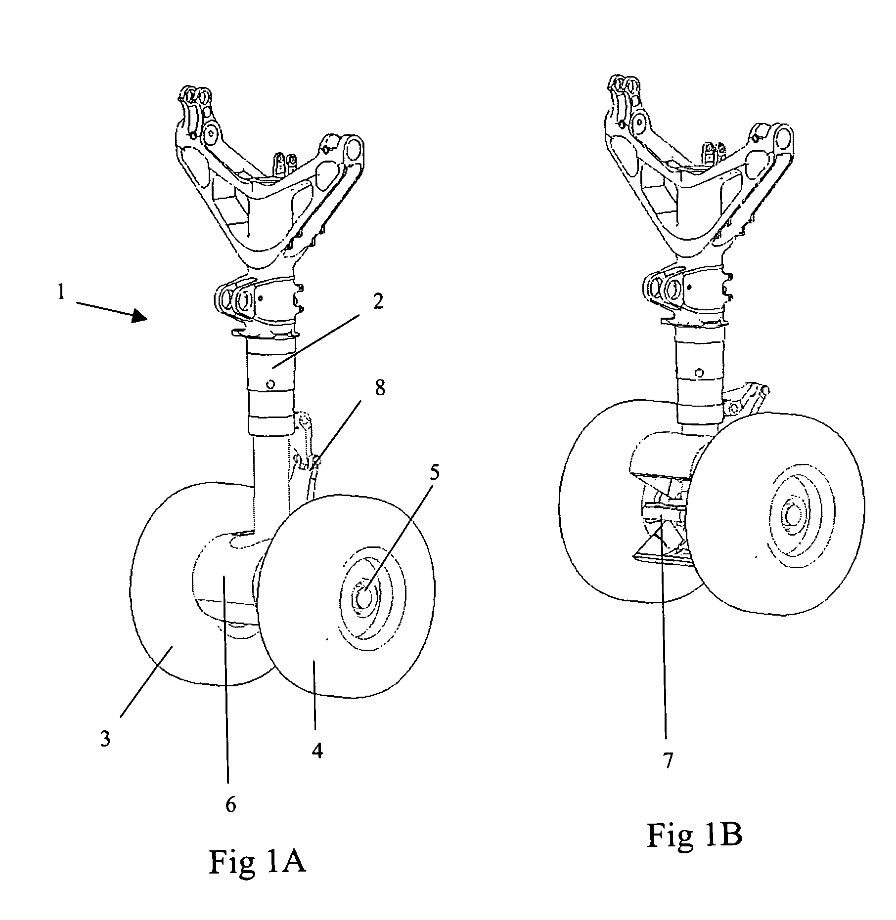
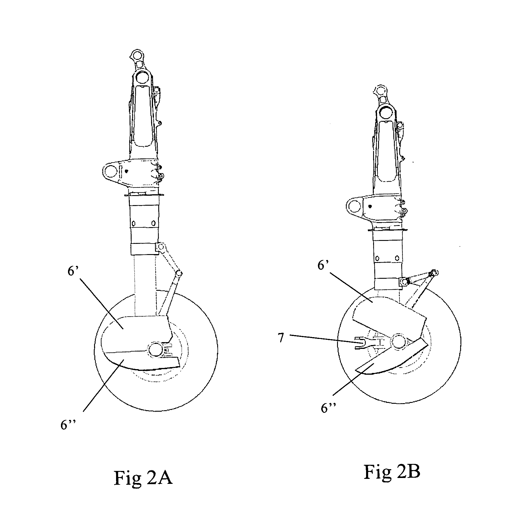
[0019]FIGS. 1A and 1B show a nose landing gear 1 of an aircraft, comprising a main telescopic leg 2, wheels 3, 4, an axle 5, a noise reducing attachment 6, a tow bar attachment 7 and an actuating apparatus including a torgue link 8. The torque link 8 is attached to the top section of the main telescopic leg 2 and the lower part of the landing gear.

[0020]In FIG. 1A the landing gear 1 is unloaded and the main telescopic leg 2 is in an extended position. This means that the aircraft to which the landing gear 1 belongs is in the air. The torque link 8 forms part of a hydraulic circuit which is arranged such that when the landing gear 1 is in the unloaded position the noise reducing attachment 6 is in a first position in which it deflects air away from the tow bar 7.

[0021]In FIG. 1B the landing gear 1 is loaded and the main telescopic leg 2 is in a compressed position. This means that the aircraft to which the landing gear belongs is on the ground. The torque link 8 has also been compres...


PUM


Abstract

The invention relates to aircraft noise reduction apparatus, in particular, but not exclusively, to noise reduction apparatus on an aircraft landing gear. The aircraft noise reduction apparatus comprises a noise reduction attachment for a landing gear of an aircraft. The noise reduction apparatus is movable between a first position in which it deflects air away from a noise inducing component of the landing gear and a second position in which it allows access to the noise inducing component. The movement of the noise reduction attachment between the first and second positions is actuated by a part of the landing gear.

Description

BACKGROUND OF THE INVENTION[0001]The invention relates to aircraft noise reduction apparatus, in particular but not exclusively, to aircraft noise reduction apparatus on an aircraft landing gear.[0002]It is increasingly important to reduce the noise created by aircraft when landing or taking off from an airport. In particular, when an aircraft is landing, developments in aircraft technology mean the aircraft engine noise has been significantly reduced. The dominant noise created by some aircraft when landing, as perceived at ground level, is starting to become the airframe noise. In order to reduce airframe noise the use of noise reduction apparatus, or fairings, is known. For example, U.S. Pat. No. 6,619,587 discloses a fairing for an aircraft landing gear, the fairing placed to deflect air away from noise inducing components of the landing gear.[0003]However, if using a fairing as disclosed in U.S. Pat. No. 6,619,587 it may become necessary for the ground crew at an airport to acc...

Claims


Application Information

Patent Timeline
Patent Type & Authority Applications(United States)
IPC IPC(8): B64C23/00B64C1/40B64C25/04
CPCB64C7/00B64C2025/003B64C25/001
Inventor CHOW, LEUNG CHOIWOOD, CHRISTOPHER NEILCAMPBELL, PHILIP
Owner AIRBUS OPERATIONS LTD
Why Eureka
Try Eureka