Adjustable landing gear system

a technology of landing gear and adjustment, which is applied in the direction of landing gear, transportation and packaging, undercarriage, etc., can solve the problems of increasing the applied force of the aircraft during landing, requiring more stowage space in the aircraft, and most aircraft are unable to achieve liftoff, etc., to achieve the effect of shortening the shock stru

Active Publication Date: 2009-12-31
THE BF GOODRICH CO
View PDF11 Cites 40 Cited by
  • Summary
  • Abstract
  • Description
  • Claims
  • Application Information

AI Technical Summary

Benefits of technology

[0010]According to yet another aspect of the invention, a method of operating a landing gear system of an aircraft includes the steps of (1) moving the landing gear system to a deployed configuration with the shock strut in a de-hiked configuration relative to the aircraft; (2) actuating a linkage member to urge the shock strut from the de-hiked configuration to a hiked configuration while the aircraft is static, the linkage member having a first end portion coupled to a telescoping cylinder of the shock strut and a second end portion coupled to the aircraft in a location aft of where the shock strut is coupled to the aircraft; and (3) while retracting the landing gear system from the deployed configuration to a stowed configuration, shortening the shock strut through operation of a kinematic relationship between the linkage member and the shock strut.

Problems solved by technology

Nevertheless, most aircraft are unable to achieve liftoff until the actual takeoff speed is achieved because the sum of the nose down thrust couple and aircraft inertial moment about the main wheel axis exceeds the available, nose-up aerodynamic control moment.
However, some drawbacks of such a fixed length extension are that it increases the applied forces to the aircraft during landing and it requires more stowage space within the aircraft when retracted.

Method used


Image

  • Adjustable landing gear system
  • Adjustable landing gear system
  • Adjustable landing gear system

Examples


Embodiment Construction

[0018]In the following description, certain specific details are set forth in order to provide a thorough understanding of various embodiments of the invention. However, one skilled in the art will understand that the invention may be practiced without these details. In other instances, well-known structures associated with landing gear systems and the assembly and operation thereof have not necessarily been shown or described in detail to avoid unnecessarily obscuring descriptions of the embodiments of the invention.

[0019]Unless the context requires otherwise, throughout the specification and claims which follow, the word “comprise” and variations thereof, such as, “comprises” and “comprising” are to be construed in an open, inclusive sense, that is as “including, but not limited to.”

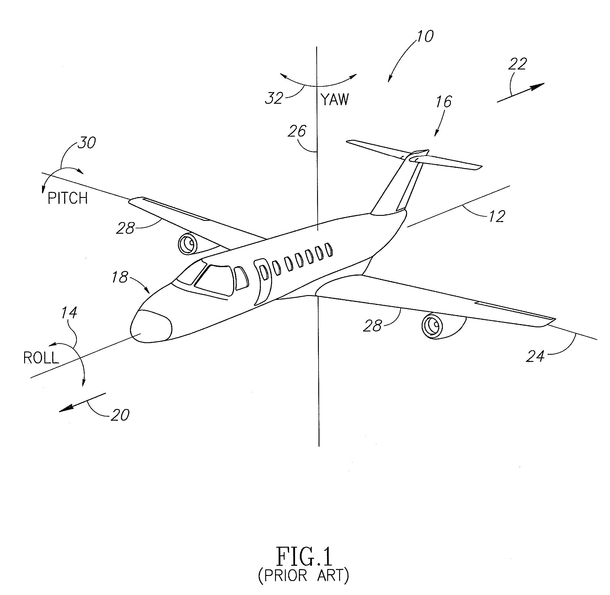
[0020]In addition, throughout the specification and claims which follow, the word “longitudinal” is meant as a broad term that relates a length of an item. By way of example, FIG. 1 shows an aircraft 1...


PUM


Abstract

A landing gear system includes a shock strut assembly and a linkage member coupled to an aircraft. Preferably, the shock strut assembly and linkage member are oriented or angled relative to one another in a non-parallel relationship. Actuation of the linkage member moves the shock strut from a de-hiked to a hiked configuration or vice-versa. In addition, the orientation of the linkage member relative to the shock strut assembly permits it to automatically move the shock strut assembly to the de-hiked position during retraction of the landing gear system and prevents the shock strut assembly from exceeding a desired length during retraction. The linkage member may take the form of a hydraulic actuator having a lower end portion coupled to an inner cylinder of the shock strut assembly and an upper end portion coupled to the aircraft aft of where the shock strut assembly is coupled to the aircraft.

Description

PRIORITY CLAIM[0001]This application claims priority to U.S. Provisional Patent Application No. 61 / 075,484 (filed on Jun. 25, 2008), and wherein its subject matter is incorporated herein by reference in its entirety.FIELD OF THE INVENTION[0002]The present invention relates generally to aircraft landing gear, and more specifically to an adjustable landing gear system.BACKGROUND OF THE INVENTION[0003]During takeoff, many aircraft have an engine thrust to aircraft weight ratio and a wing aspect ratio that generates a sufficient amount of lift to allow the aircraft to fly at a speed less than the actual takeoff speed. Nevertheless, most aircraft are unable to achieve liftoff until the actual takeoff speed is achieved because the sum of the nose down thrust couple and aircraft inertial moment about the main wheel axis exceeds the available, nose-up aerodynamic control moment.[0004]Some proposals for allowing an aircraft to takeoff at a lower speed have included fixed length extensions in...

Claims


Application Information

Patent Timeline
Patent Type & Authority Applications(United States)
IPC IPC(8): B64C25/10
CPCB64C2025/008B64C25/14
Inventor LUCE, WILLIAM E.WILSON, PHILLIP K.DAVIS, JONATHON R.
Owner THE BF GOODRICH CO
Why Eureka
Try Eureka