Installation and method for harnessing wave energy

a technology of installation and method, applied in the field of offshore systems can solve the problems of poor efficiency of energy potential, social rejection of environmental impact, and large environmental impact of on-shore systems and methods for converting wave energy, so as to minimise maintenance costs, facilitate mooring, and maximise energy extraction

Inactive Publication Date: 2009-12-31
OCEANTEC ENERGIAS MARINAS
View PDF4 Cites 30 Cited by
  • Summary
  • Abstract
  • Description
  • Claims
  • Application Information

AI Technical Summary

Benefits of technology

[0011]The object of the present invention is an off-shore installation or floating system for harnessing wave energy, of the attenuator type and with an inertial relative motion based on a flywheel that solves the aforementioned drawbacks. This installation is easily moored and is designed to maximise the energy e

Problems solved by technology

However, on-shore systems and methods for converting wave energy suffer from certain drawbacks, foremost among which are the poor efficiency of the energy potential, their great environmental impact and the social rejection of said environmental impact.
Submerged off-shore systems have the drawback that the off-shore energy distribution decreases exponentially with the distance to the surface.
However, most floating off-shore systems require a fixed reference for their operation (anchoring to sea base or ballast), which increases the mooring loads.
In addition, these devices are sensitive to tides and their installati

Method used


Image

  • Installation and method for harnessing wave energy
  • Installation and method for harnessing wave energy
  • Installation and method for harnessing wave energy

Examples


Embodiment Construction

[0049]Described below with reference to the figures are the various embodiments of the installation or system of the present invention.

[0050]In addition, the term “approximately” must be understood as specifying values that are very close to those stated. An expert in the art will understand that a small deviation in the values specified, within reasonable margins, is inevitable due to measurement inaccuracies, etc.

[0051]Furthermore, in the context of the present invention the following terms must be interpreted as defined below:

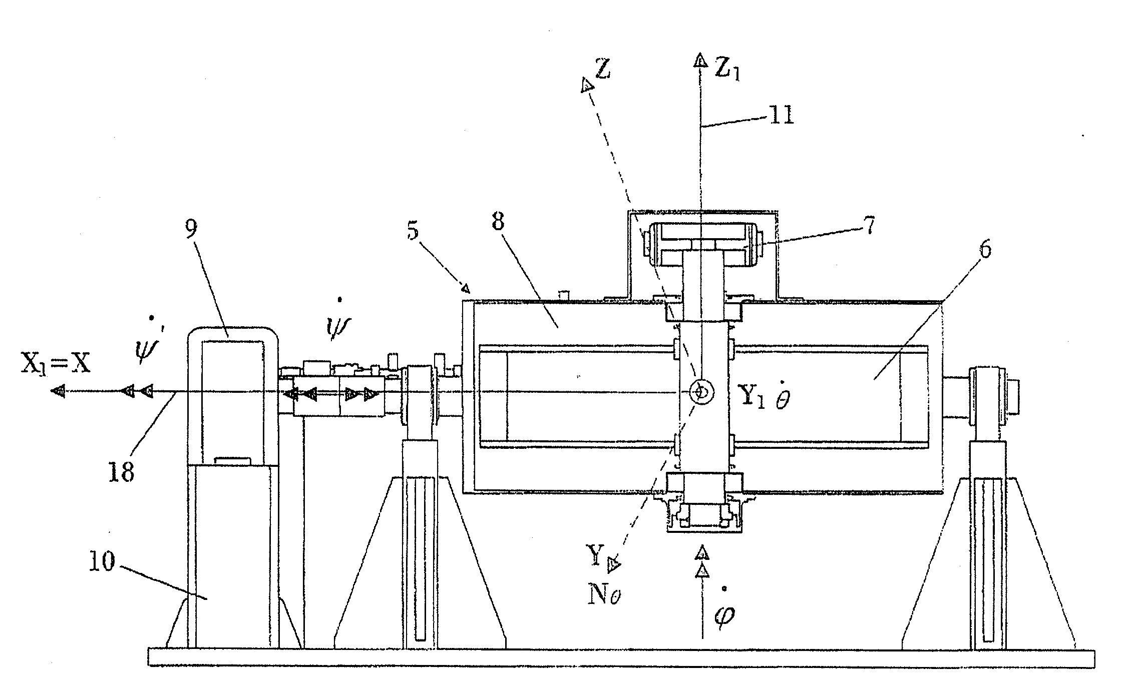
[0052]The terms “pitch” and “roll” must be interpreted according to the conventions used in naval engineering. The reference coordinate system is placed with the X-axis towards the prow of the energy converter, the Y-axis towards the port side and the Z-axis upward. The origin of the coordinates is placed in the centre of gravity of the converter.

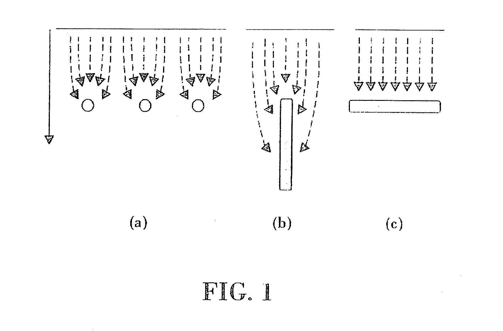
[0053]To illustrate these concepts, FIG. 20 shows the convention used in naval engineering: When a wave front mov...


PUM


Abstract

Installation for harnessing wave energy, comprising a floating structure (1) that comprises at least one gyroscopic device (5) with a flywheel (6) that can turn by the action of a motor (7) and a generator (10) configured so that when the gyroscopic device (5) is in use, said flywheel (6) is subjected to a pitching torque caused by the motion of the waves that feeds the generator (10), wherein the installation also comprises: means (23, 44) for controlling the motor (7); means (24,45) for controlling the generator (10); a floating device (25) for capturing data on the waves; means for transmitting the data captured by the data-capturing floating device (25) and for receiving said data in the floating structure (1); a control unit (16) that calculates at least one parameter applicable by the means (23, 44) for controlling the motor (7) and at least one parameter applicable by the means (24, 45) for controlling the generator (10).

Description

FIELD OF THE INVENTION[0001]The present invention belongs to the field of systems for converting wave energy. More specifically, the present invention relates to an off-shore system for converting wave energy.BACKGROUND OF THE INVENTION[0002]Efforts have been made for a long time to harness the energy generated by ocean waves. Among the methods used traditionally for this purpose are on-shore systems.[0003]However, on-shore systems and methods for converting wave energy suffer from certain drawbacks, foremost among which are the poor efficiency of the energy potential, their great environmental impact and the social rejection of said environmental impact.[0004]To overcome these drawbacks, off-shore methods and systems have been proposed for harnessing wave energy. Off-shore systems can be of two types, submerged or based on floating structures. Submerged off-shore systems have the drawback that the off-shore energy distribution decreases exponentially with the distance to the surfac...

Claims


Application Information

Patent Timeline
IPC IPC(8): H02P9/04F03B13/14
CPCF03B13/16Y02E10/38F03G3/08F03B13/20Y02E10/30F05B2250/44F05B2270/202
Inventor RUIZ MINGUELA, JOSE PABLOELORDUIZAPATARIETXE FADRIQUE, SABINOHERRERO EIZMENDI, MARIALIRIA LOZA, PEDRO
Owner OCEANTEC ENERGIAS MARINAS
Why Eureka
Try Eureka