Natural energy extraction apparatus

a technology of natural energy extraction and mooring apparatus, which is applied in the direction of renewable energy generation, sustainable manufacturing/processing, greenhouse gas reduction, etc., can solve the problems of increasing production cost, increasing the size of float and mooring apparatus, and complicated internal structure of float, so as to reduce the cost of mooring

Active Publication Date: 2018-08-14
ALBATROSS TECH LLC
View PDF42 Cites 3 Cited by
  • Summary
  • Abstract
  • Description
  • Claims
  • Application Information

AI Technical Summary

Benefits of technology

[0008]In the energy extraction apparatus of the present invention, the second float corresponding to the float of the conventional natural energy extraction apparatus does not need an apparatus for supporting the first float because the vertical rotating shaft is the first float and is supported by buoyancy of water. The second float corresponding to the float of the conventional natural energy extraction apparatus does not need to prevent swing of the first float because inherent swinging of the first float is anticipated. A power transmission device is disposed in an open space between the first float and the second float. Therefore, the internal structure of the second float corresponding to the float of the conventional natural energy extraction apparatus becomes simpler than that of the float of the conventional natural energy extraction apparatus, the second float and the mooring apparatus become more compact than those of the conventional natural energy extraction apparatus, and production cost of the second float becomes lower than that of the float of the conventional natural energy extraction apparatus. The driven equipment is, for example, a power generator, a pump, a compressor, a flywheel for energy storage, etc.
[0053]When the pair of first floats are rotated in opposite directions during operation of the energy storage apparatus, rotational torques transmitted from the generators to the second float cancel each other and rotation of the second float is prevented. As a result, mooring of the second float becomes easy and mooring cost decreases.

Problems solved by technology

The offshore wind energy extraction apparatus of Patent Document No. 1 has problems, including, inter alia, that installation of supporting members for rotatably supporting the vertical rotating shaft and the power generator in the float makes the internal structure of the float complicated and increases production cost and that an attempt to make the vertical rotating shaft stand vertically as desired increases the sizes of the float and a mooring apparatus, etc.

Method used


Image

  • Natural energy extraction apparatus
  • Natural energy extraction apparatus
  • Natural energy extraction apparatus

Examples


Embodiment Construction

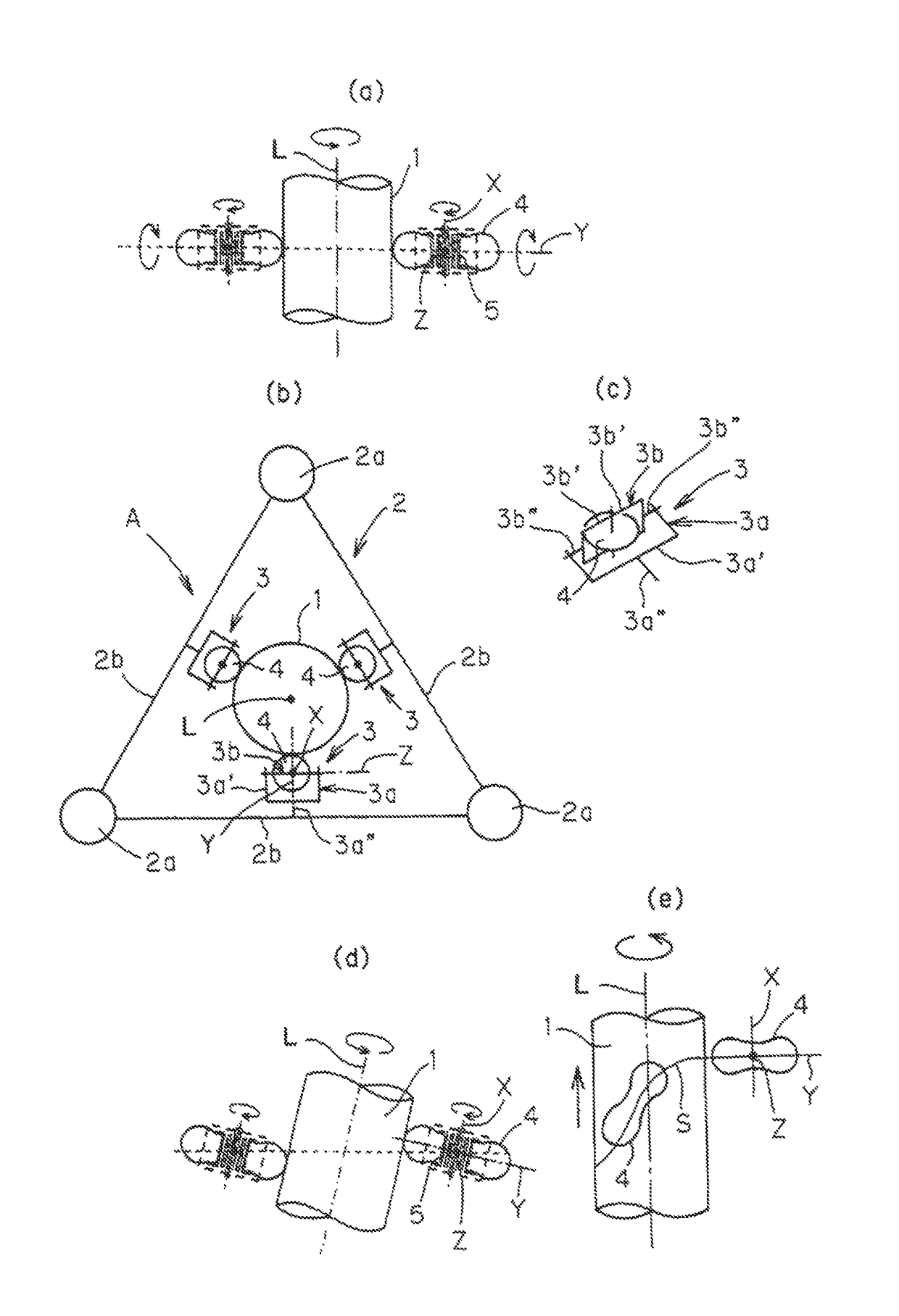
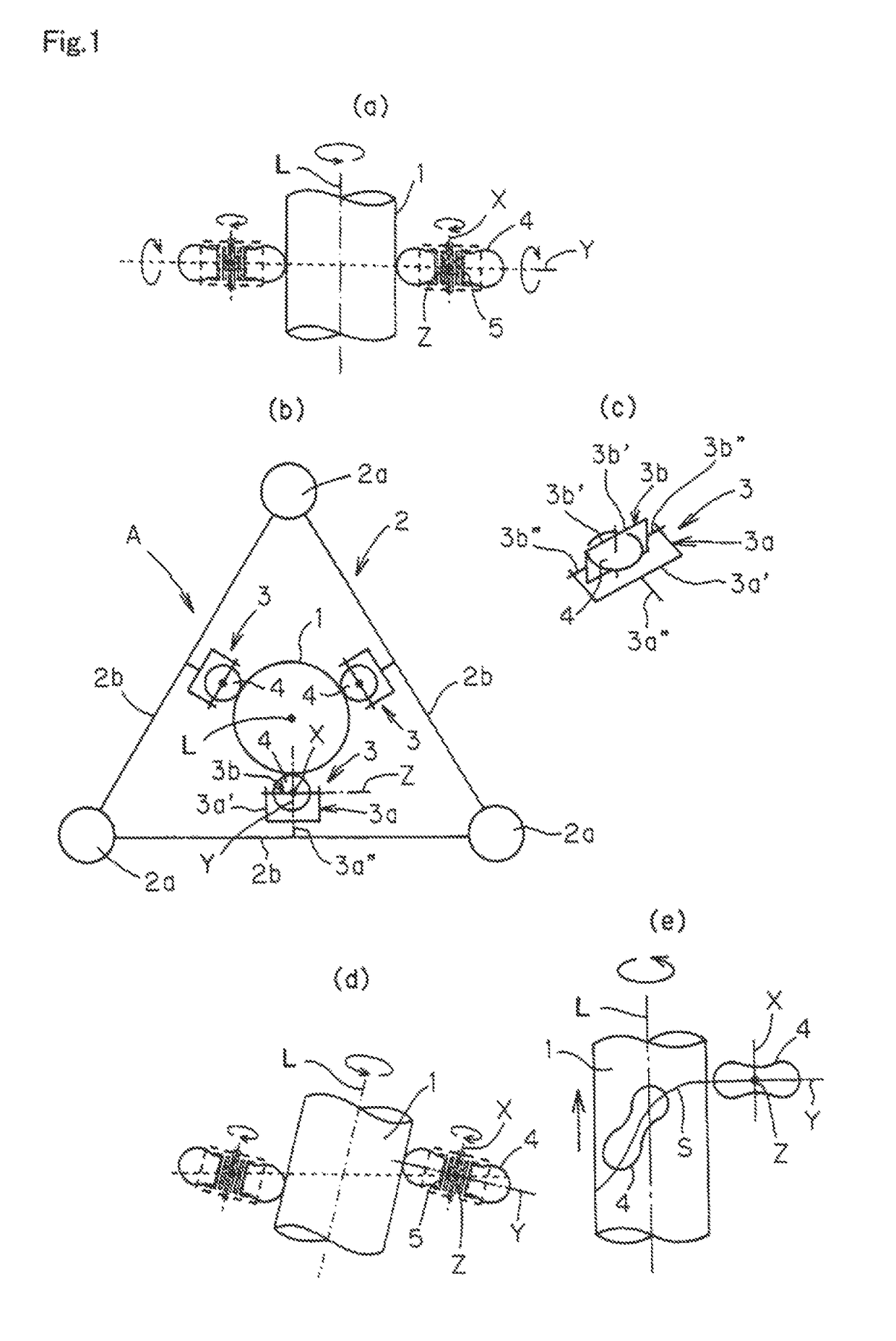
[0063]Natural energy extraction apparatuses in accordance with preferred embodiments of the present invention will be described.

[0064]As shown in FIGS. 1(a), 1(b) and 1(c), a natural energy extraction apparatus A comprises a first float 1 of circular cylindrical shape forming a vertical rotating shaft, i.e., a vertically extending rotating shaft, and a second float 2 moored on a body of water to surround the first float 1.

[0065]The second float 2 comprises three floats 2a of circular cylindrical shape and three arm members 2b for connecting each adjacent pair of floats 2a. Each float 2a is located at one of three apexes of an equilateral triangle, at the center of which the first float 1 is located as seen from above. The arm members 2b are located in the same plane.

[0066]A support arm 3 is attached to the longitudinal middle of each arm member 2b. The support arm 3 comprises a first portion 3a of tuning fork shape and a second portion 3b of the shape of a pair of integrally united ...


PUM


Abstract

An object of the present invention is to provide a natural energy extraction apparatus comprising a vertical rotating shaft and a float for supporting the vertical rotating shaft, wherein the internal structure of the float is simpler, the float and a mooring apparatus are more compact, and production cost is lower than in the conventional natural energy extraction apparatus. A natural energy extraction apparatus comprises a first float forming a swingable vertical rotating shaft, a second float moored to surround the first float, and a power transmission device attached to the second float to convert rotational kinetic energy of the first float to driving torque for driven equipment, and the natural energy extraction apparatus is installed on a body of water.

Description

[0001]This is a National Phase Application in the United States of International Patent Application No. PCT / JP2012 / 063815 filed May 29, 2012, which claims priority on Japanese Patent Application Nos. 2011-123225, filed Jun. 1, 2011 and 2011-149016, filed Jul. 5, 2011. The entire disclosures of the above patent applications are hereby incorporated by reference.TECHNICAL FIELD[0002]The present invention relates to a natural energy extraction apparatusBACKGROUND ART[0003]Patent document No. 1 discloses an offshore wind energy extraction apparatus comprising a vertical rotating shaft, a float for supporting the vertical rotating shaft, and a power generator installed in the float to operably engage the vertical rotating shaft and be rotated by the vertical rotating shaft, wherein the float is moored on a body of water.PRIOR ART DOCUMENTPatent Document[0004]Patent Document No. 1: WO03 / 089787DISCLOSURE OF INVENTIONProblem to be Solved[0005]The offshore wind energy extraction apparatus of ...

Claims


Application Information

Patent Timeline
Patent Type & Authority Patents(United States)
IPC IPC(8): F03D9/00F03D3/00F03D7/06F03B17/06F03D13/20
CPCF03D9/00F03B17/063F03D3/005F03D7/06F03D13/22F03B17/06Y02P70/527F05B2240/93F05B2240/95Y02E10/223Y02E10/28Y02E10/38Y02E10/727Y02E10/74Y02P70/523F05B2260/904F05B2270/1011Y02E60/16Y02E10/20Y02E10/30Y02P70/50Y02E70/30F03B7/00F03D3/02F03D9/008F03D80/30F03D9/11F03D9/25F03D15/00
Inventor AKIMOTO, HIROMICHI
Owner ALBATROSS TECH LLC
Why Eureka
Try Eureka