Torque transmission for an aircraft engine

a technology for aircraft engines and torque transmissions, applied in the direction of engine starting, electric generator control, gearing, etc., can solve problems such as associated weight penalties, and achieve the effect of reducing transmission ratio and transmission ratio

Active Publication Date: 2009-12-31
PRATT & WHITNEY CANADA CORP
View PDF58 Cites 31 Cited by
  • Summary
  • Abstract
  • Description
  • Claims
  • Application Information

AI Technical Summary

Problems solved by technology

However, when the engine is running, the operating speed of the engine can be many times the starting speed and a smaller-sized starter may need to be disconnected from the engine to prevent it from overspeeding.
If the electrical machine remains continuously connected to the engine spool shaft, concessions in machine design need to be made in order to allow a sufficiently robust machine to operate in both starting and generating conditions, which results in associated weight penalties.

Method used


Image

  • Torque transmission for an aircraft engine
  • Torque transmission for an aircraft engine
  • Torque transmission for an aircraft engine

Examples


Embodiment Construction

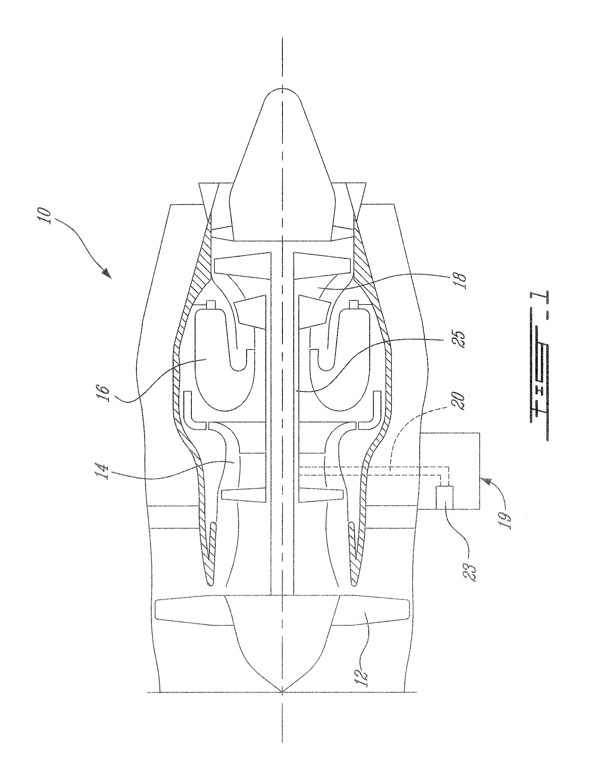
[0012]FIG. 1 illustrates an example of a gas turbine engine 10 generally comprising in serial flow communication a fan 12 through which ambient air is propelled, a multistage compressor 14 for pressurizing the air, a combustor 16 in which the compressed air is mixed with fuel and ignited for generating an annular stream of hot combustion gases, and a turbine section 18 for extracting energy from the combustion gases. A high pressure compressor-turbine shaft 25 is connected by a transmission 20 (presented rather schematically in FIG. 1) to an electric starter-generator 23, located in this example on an accessory gearbox 19. This figure only illustrates one example of a suitable environment in which the present system and method may be used.

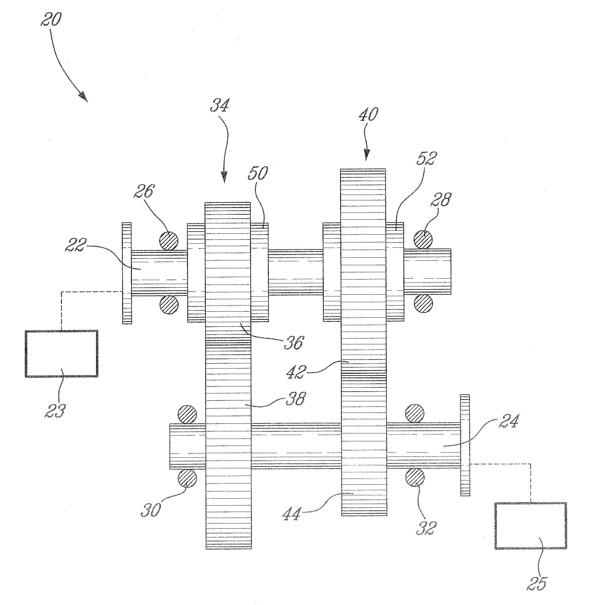
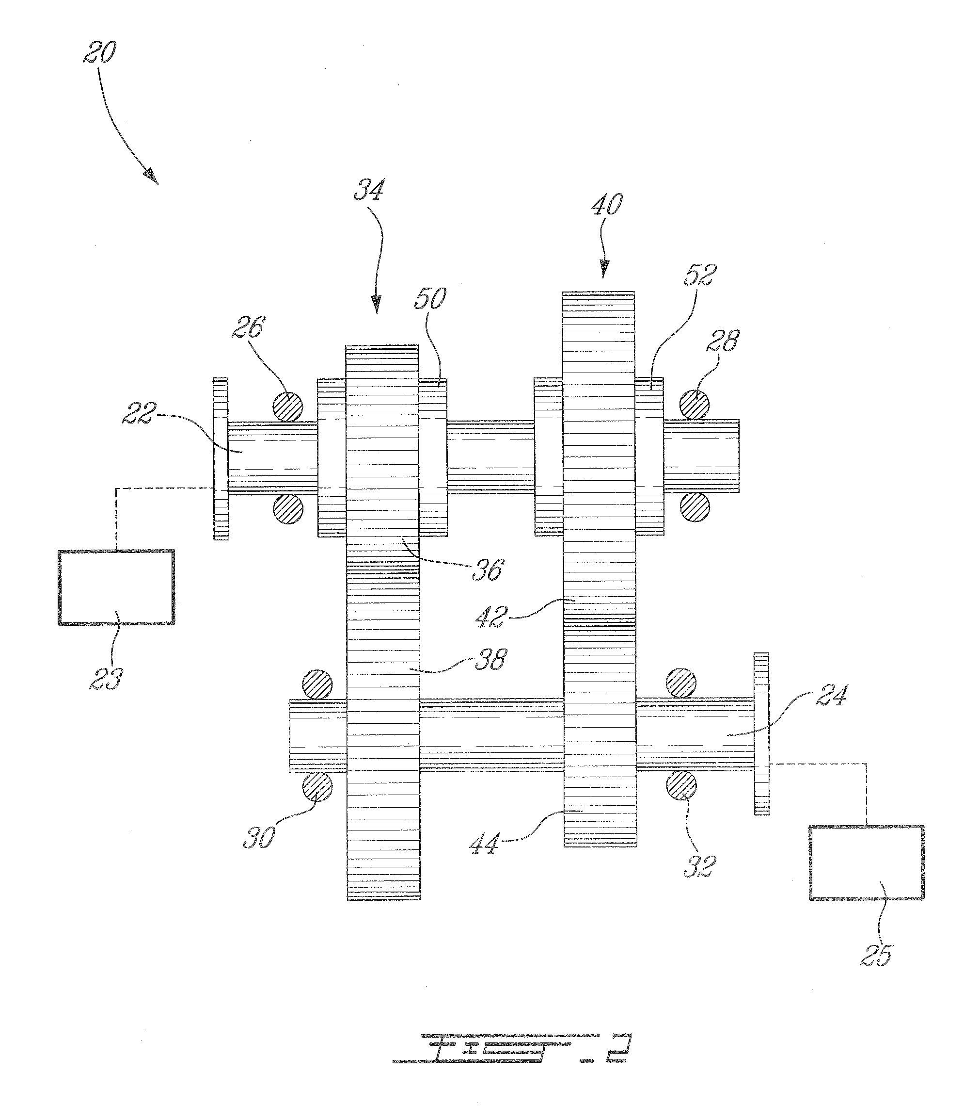
[0013]FIG. 2 shows an example of a torque transmission system 20 as improved. This system 20 is designed to be used in the gas turbine engine 10. It comprises a first input / output shaft 22 and a second input / output shaft 24. Both shafts 22, 24 are ...


PUM


Abstract

The torque transmission system for an aircraft engine permits a starter-generator to drive the engine on starting at a speed reducing ratio. Once the engine is running, the engine then drives the starter-generator also at a speed reducing ratio.

Description

TECHNICAL FIELD[0001]The field of invention generally relates to a torque transmission arrangement and to a method of providing a speed reduction between a starter-generator and an aircraft engine.BACKGROUND OF THE ART[0002]When starting an aircraft engine such as a gas turbine engine, it is desirable to use an electric starter operating at the highest optimum speed since the starter motor can then have a smaller and a lighter construction compared to a motor operating at a lower rotation speed. However, when the engine is running, the operating speed of the engine can be many times the starting speed and a smaller-sized starter may need to be disconnected from the engine to prevent it from overspeeding. If the electrical machine remains continuously connected to the engine spool shaft, concessions in machine design need to be made in order to allow a sufficiently robust machine to operate in both starting and generating conditions, which results in associated weight penalties. Room...

Claims


Application Information

Patent Timeline
Patent Type & Authority Applications(United States)
IPC IPC(8): H02K23/52F16H37/06
CPCF02C7/275F02C7/36F05D2220/76F05D2260/85F05D2270/061Y02T50/60Y10T74/19177
Inventor DOOLEY, KEVIN ALLAN
Owner PRATT & WHITNEY CANADA CORP
Why Eureka
Try Eureka