Image Forming Appartaus

Active Publication Date: 2009-12-31
BROTHER KOGYO KK
View PDF11 Cites 11 Cited by
  • Summary
  • Abstract
  • Description
  • Claims
  • Application Information

AI Technical Summary

Benefits of technology

[0008]Therefore, an advantage of the invention is to improve image quality by suppressing a variation in gap in the optical axis direction between the photosensitive member and the exposure member.
[0009]This and other advantages of the invention will be discussed with reference to the accompanying drawings.

Problems solved by technology

As a result, since a focal position of light emitted from the LED head is changed, the image quality is deteriorated.

Method used


Image

  • Image Forming Appartaus
  • Image Forming Appartaus
  • Image Forming Appartaus

Examples


first embodiment

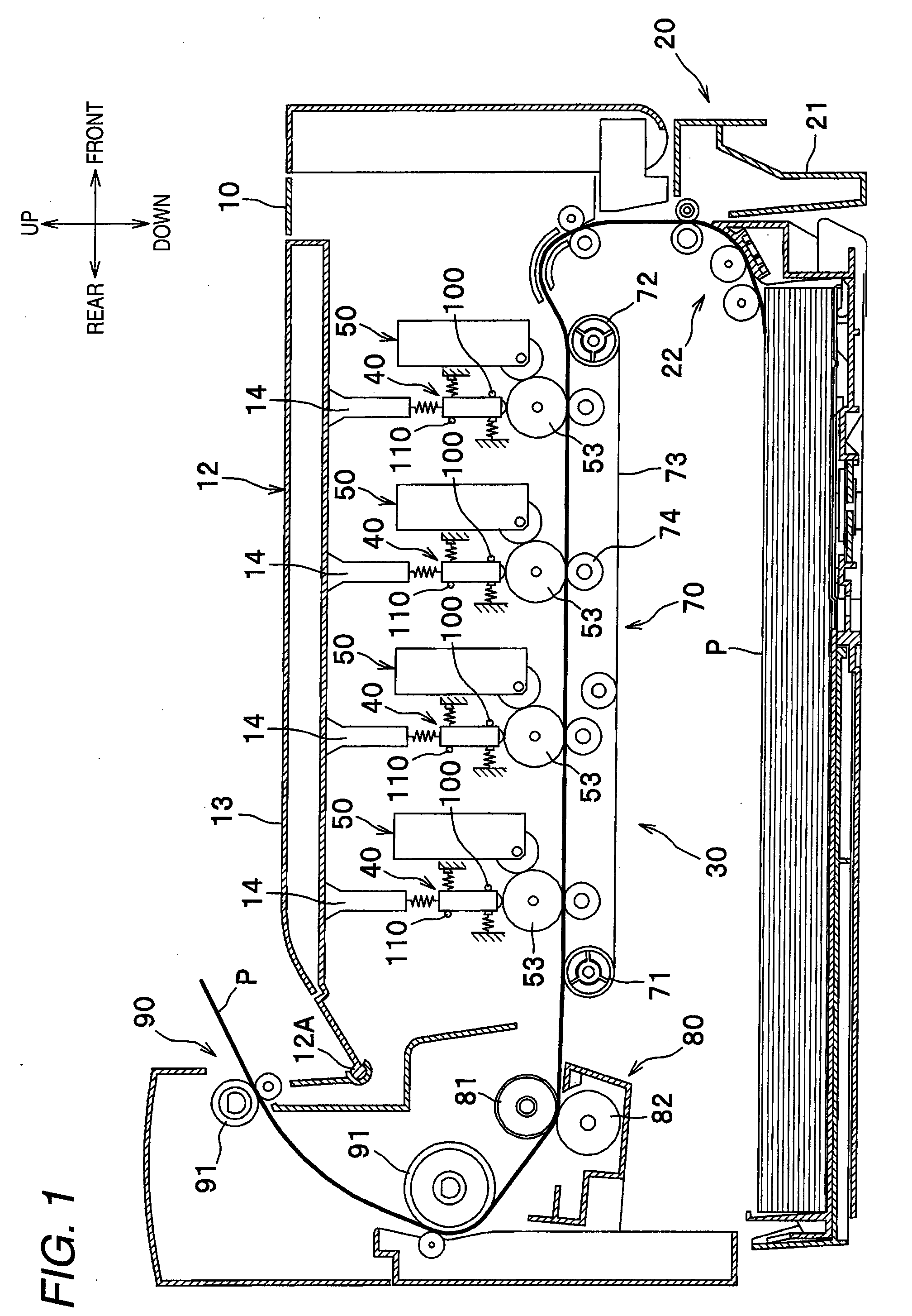
[0022]A first embodiment of the invention will be described in detail with reference to the accompanying drawings. FIG. 1 is a sectional view illustrating the entire configuration of a color printer.

[0023]In the following description, directions are described based on a user using the color printer. That is, in FIG. 1, the right side as facing the plane of paper is “front (near side)”, the left side as facing the plane of paper is “rear (deep side)”, the deep side as facing the plane of paper is “right”, and the near side as facing the plane of paper is “left.” The vertical direction as facing the plane of paper is “vertical direction.”

[0024]As shown in FIG. 1, the color printer 1 includes a sheet feed unit 20 feeding a sheet P, an image forming unit 30 forming an image on the fed sheet P, and a sheet discharge unit 90 discharging the sheet P having the image formed thereon in a main chassis 10.

[0025]The upper portion of the main chassis 10 is provided with an upper cover 12 being f...

second embodiment

[0094]A second embodiment of the invention will be described in detail with reference to FIGS. 7 to 12. FIG. 7 is a sectional view illustrating the entire configuration of a color printer. Elements of the second embodiment having the same functions as the elements of the first embodiment will be referenced by like reference numerals and the repeated description thereof will be omitted.

[0095]Configuration of Positioning Member

[0096]FIGS. 8(a), 8(b), and 8(c) are diagrams illustrating the configuration of the positioning member 100 according to the second embodiment, where FIG. 8(a) is a side view illustrating a state where the positioning member is not abraded, FIG. 8(b) is a rear view of the positioning member as viewed from the rear side, and FIG. 8(c) is a side view illustrating a state where the positioning member is abraded. FIG. 9 is a side view illustrating an angle formed by a straight line connecting a contact point of the photosensitive drum with the guide rollers and the c...


PUM


Abstract

An image forming apparatus is provided, which includes: a photosensitive member; an exposure member; a gap keeping member; a positioning member and a swing regulating member. The swing regulating member is configured to come in contact with the exposure member at a contact position that is more upstream than the exposure member and that is more separated from the photosensitive member than a contact position between the positioning member and the exposure member.

Description

CROSS REFERENCE TO RELATED APPLICATION[0001]The present disclosure relates to the subject matter contained in Japanese Patent Application Nos. 2008-170819 (filed on Jun. 30, 2008) and 2008-171166 (filed on Jun. 30, 2008), each of which is expressly incorporated herein by reference in its entirety.TECHNICAL FIELD[0002]The present invention relates to an image forming apparatus exposing a photosensitive member such as a photosensitive drum by the use of an exposure member having plural light emitting portions such as LED heads.BACKGROUND ART[0003]JP-A-2002-361931 discloses an image forming apparatus exposing a photosensitive drum by the use of an LED head, in which a spacer maintaining a gap in an optical axis direction between the LED head and the photosensitive drum is disposed between the LED head and the photosensitive drum. In the image forming apparatus, the spacer is formed integral with the LED head.[0004]Since the spacer is formed integral with the LED head, the spacer coming...

Claims


Application Information

Patent Timeline
IPC IPC(8): B41J2/435
CPCB41J25/308G03G15/04054G03G2215/0409G03G15/326
Inventor TAMARU, YASUOYOKOI, JUNICHI
Owner BROTHER KOGYO KK
Why Eureka
Try Eureka