Light source device

a technology of light source and illumination device, which is applied in the direction of semiconductor devices, lighting and heating apparatus, instruments, etc., can solve the problems of reducing the brightness of the illumination device and the brightness of the central portion

Inactive Publication Date: 2009-12-31
HON HAI PRECISION IND CO LTD
View PDF5 Cites 10 Cited by
  • Summary
  • Abstract
  • Description
  • Claims
  • Application Information

AI Technical Summary

Problems solved by technology

When the planar light sources are positioned on glass substrates, part of lights emitted from the planar light sources will be totally refracted at peripheral portions of the substrates, which

Method used


Image

  • Light source device
  • Light source device
  • Light source device

Examples


Embodiment Construction

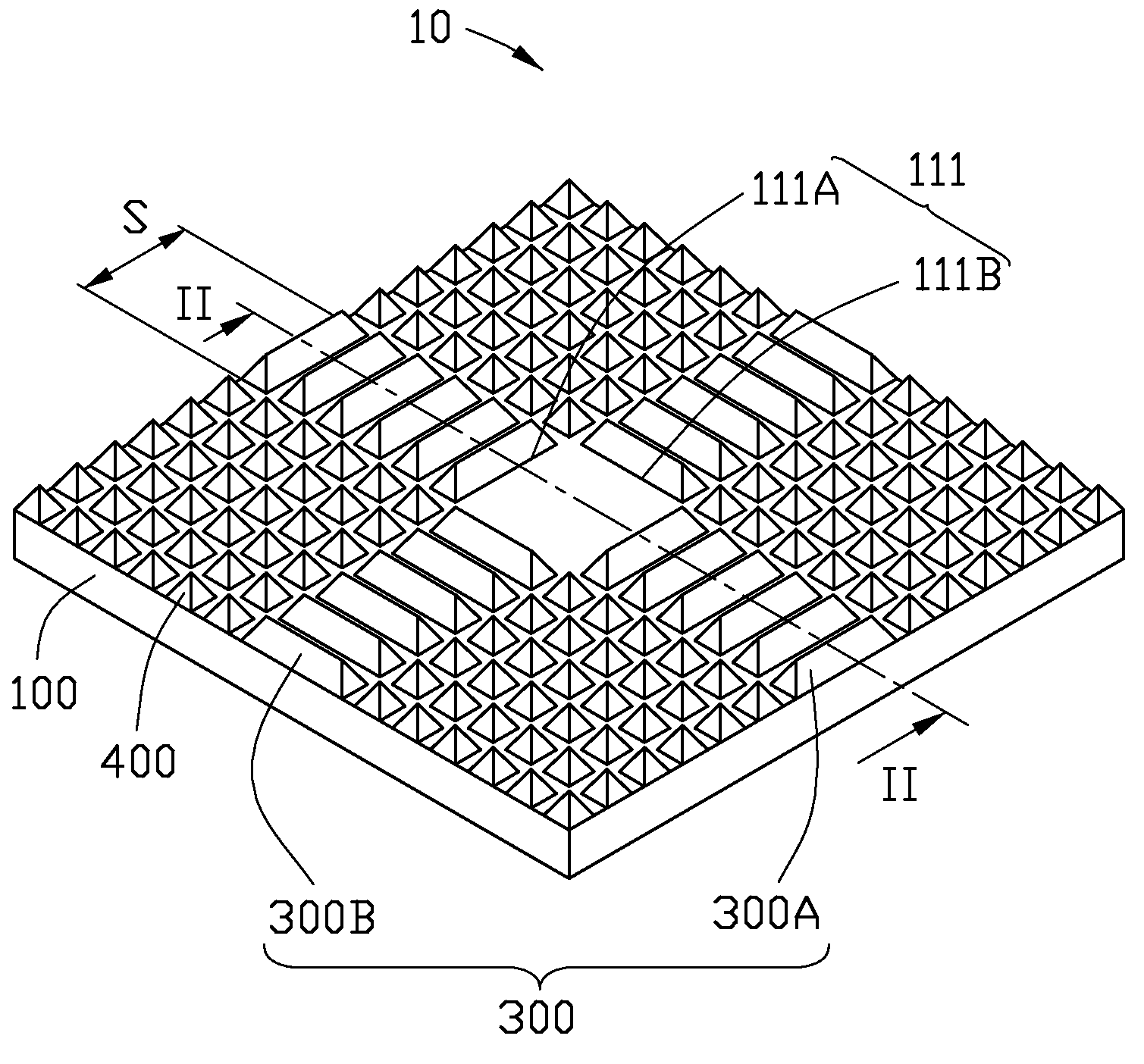
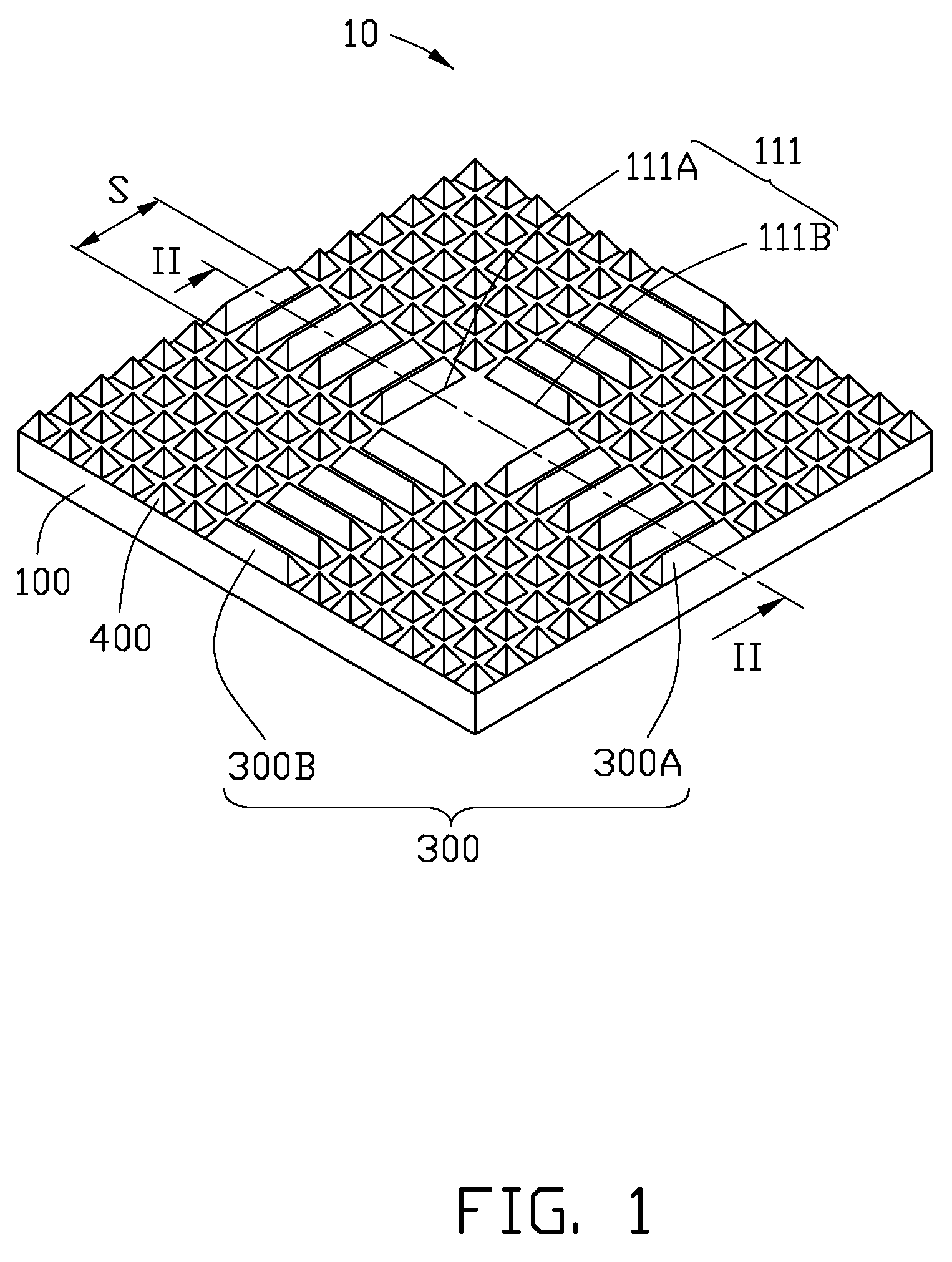
[0014]Referring to FIGS. 1 and 2, one embodiment of a light source device 10 includes a light conduction component 100, a planar light source 200, a first light diffusion component 300, and a plurality of second light diffusion components 400.

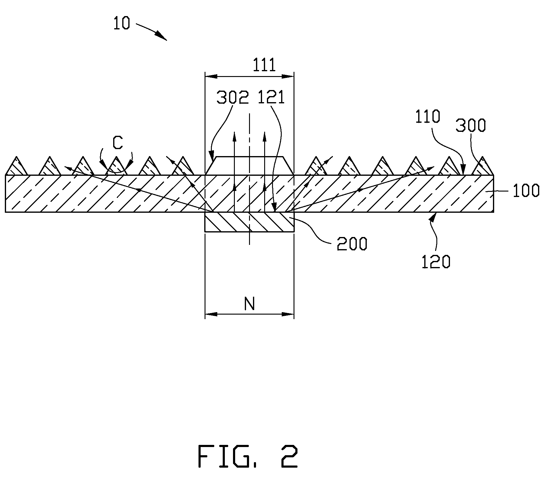
[0015]The planar light source 200 may be circular-shaped or may be rectangular shaped. In one embodiment, the planar light source 200 is square-shaped and has a width N of about 177 micrometers. The planar light source 200 includes a plurality of organic light emitting diodes.

[0016]The light conduction component 100 distributes lights emitted from the planar light source 200. The light conduction component 100 includes a first surface 110 and a second surface 120 opposite and substantially parallel to the first surface 110. The second surface 120 has a light input portion 121 positioned on a central portion of the light conduction component 100. The cross-section of the light input portion 121 is substantially identical to the cross-section of ...


PUM


Abstract

A light source device includes a light conduction, a light source and a light diffusion component. The light conduction component has a first surface and a second surface opposite to the first surface. The second surface has a light input portion. The first surface has a light output portion substantially coaxial with the light input portion and having two opposite longitudinal ends and two opposite lateral ends. The light source is configured to emit lights to the light input portion. The first light diffusion component is positioned on the first surface, and includes row light diffusion components and column light diffusion components substantially perpendicular to the row light diffusion components. The row light diffusion components are positioned at the longitudinal ends of the light output portion. The column light diffusion components are positioned at the lateral ends of the light output portion.

Description

CROSS-REFERENCE STATEMENT[0001]This application is related to a co-pending U.S. patent application (Attorney Docket No. US19717), entitled “LIGHT SOURCE DEVICE”, invented by Tsung-Yu Lin. Such application has the same inventor and assignee as the present application.BACKGROUND[0002]1. Technical Field[0003]The disclosure relates to a light source device.[0004]2. Description of Related Art[0005]Nowadays, planar light sources are widely used in light source devices. When the planar light sources are positioned on glass substrates, part of lights emitted from the planar light sources will be totally refracted at peripheral portions of the substrates, which decreases brightness of the illumination devices.[0006]A typical light source device includes a planar light source, a light conduction component and a plurality of pyramid-shaped prisms. The light conduction component is positioned between the planar light source and the pyramid-shaped prisms. The pyramid-shaped prisms can avoid tota...

Claims


Application Information

Patent Timeline
IPC IPC(8): F21V11/00G02B5/02
CPCF21K9/00G02B6/0036G02F1/133611F21Y2105/008H01L51/5275H01L2251/5361G02F2001/133607F21Y2105/00F21Y2115/15G02F1/133607H10K50/858
Inventor LIN, TSUNG-YU
Owner HON HAI PRECISION IND CO LTD
Why Eureka
Try Eureka