Lightweight surgical mesh

Inactive Publication Date: 2009-12-31
HERNIAMESH
View PDF26 Cites 43 Cited by
  • Summary
  • Abstract
  • Description
  • Claims
  • Application Information

AI Technical Summary

Benefits of technology

[0014]The first, second, third, and fourth weaves can include clear filaments and dyed filaments. The spacing between dyed fi

Problems solved by technology

However, the heavyweight mesh may cause increased patient discomfort due to the increase in scar tissue formation.
However, lightweight meshes have other drawbacks.
First, they typically have a lower minimum tensile strength due to the smaller dia

Method used


Image

  • Lightweight surgical mesh
  • Lightweight surgical mesh
  • Lightweight surgical mesh

Examples


Example

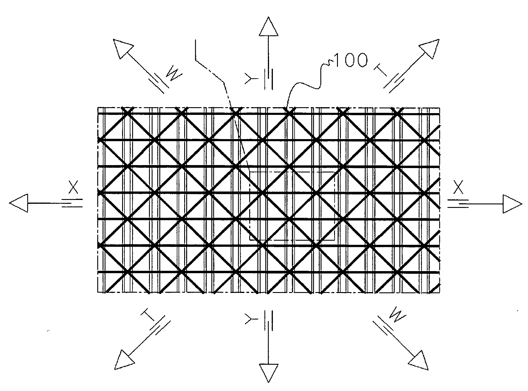
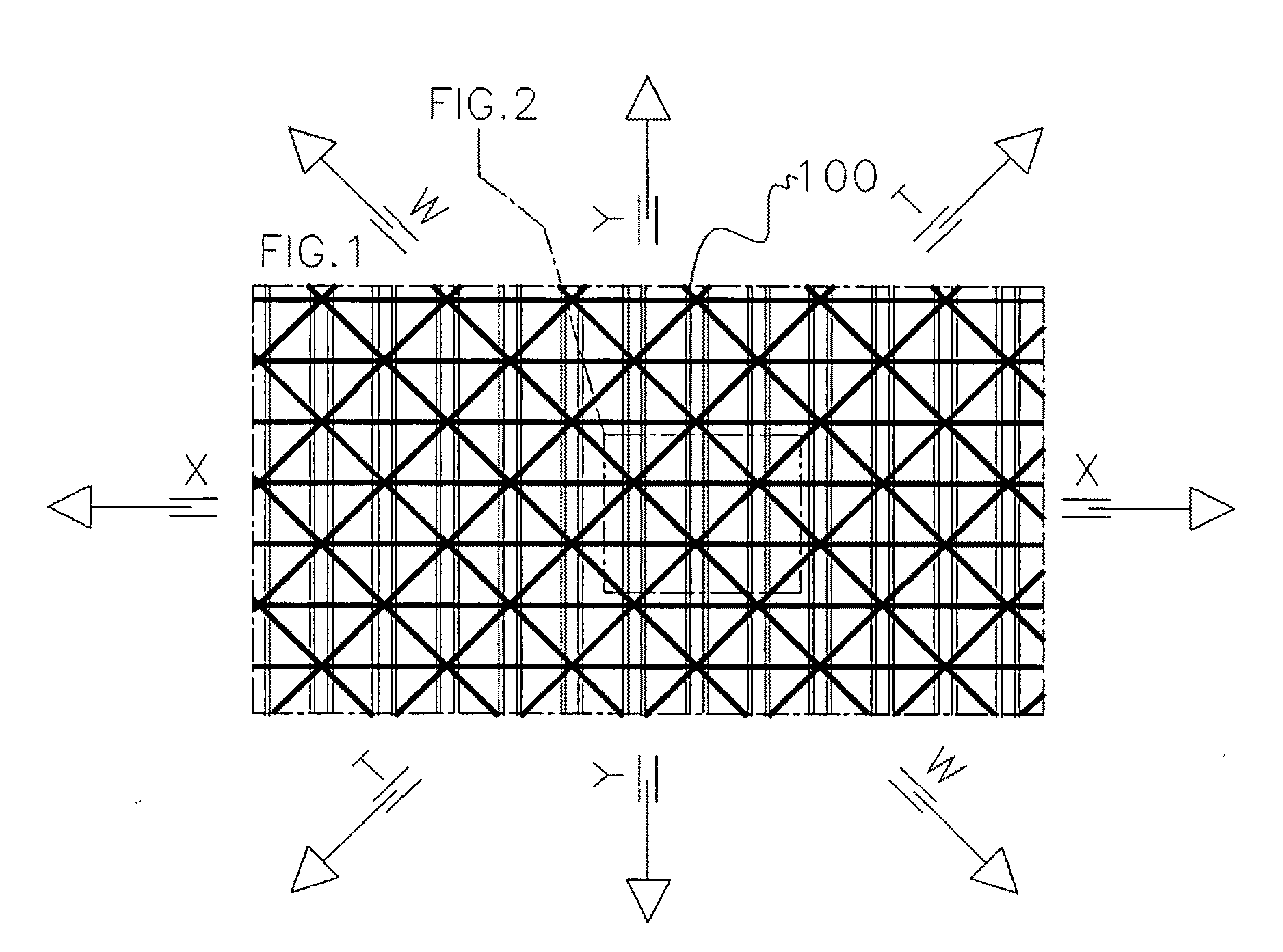
[0038]Referring to FIG. 1, a surgical mesh 100 of the present invention is illustrated. Surgical mesh 100 can be surgically implanted in a patient to treat urinary or fecal incontinence resulting from urethral hypermobility or intrinsic sphincter deficiency (ISD). Further, surgical mesh 100 can be implanted to reinforce soft tissue deficiencies. This includes, but is not limited to, pubourethral support and bladder support, urethral and vaginal prolapse repair, pelvic organ prolapse, colon and rectal prolapse repair, incontinence, reconstruction of the pelvic floor, sacral-colposuspension, abdominal wall hernias and chest wall defects. To accomplish the necessary support, mesh 100 can be made into pre-shaped designs, slings, three-dimensional plugs or flat sheets, as needed for each ailment to be corrected.

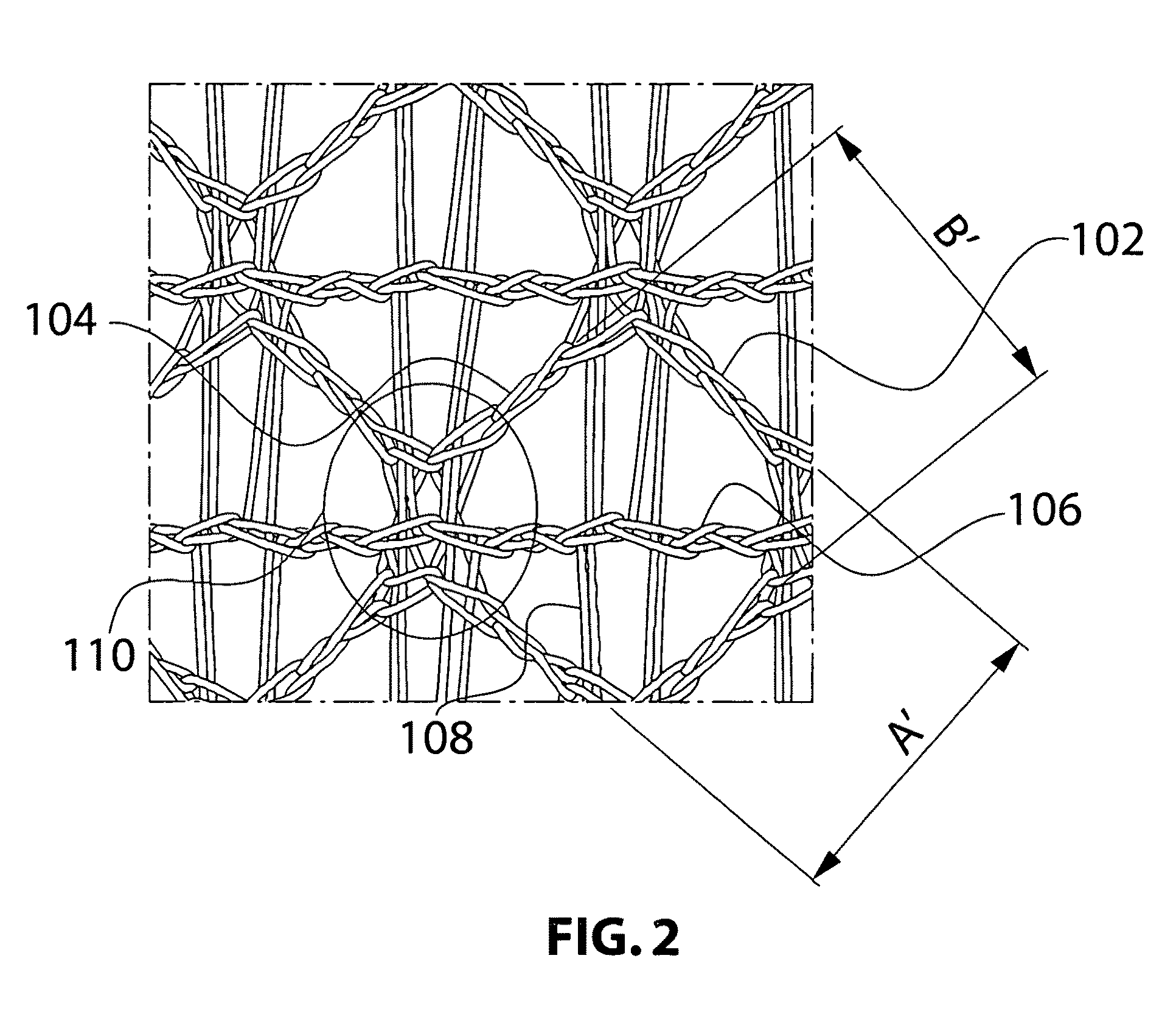
[0039]Surgical mesh 100 is a two bar warp knitted structure. The mesh 100 is subject to numerous forces in tension. Forces are typically applied to the mesh along the X and Y axes...


PUM


Abstract

A lightweight knitted surgical mesh which includes a first axis, a second axis perpendicular to the first axis, a third axis offset approximately 30° to 60° from the first axis, and a fourth axis perpendicular to the third axis. Further the mesh has a first weave running parallel to the first axis, a second weave running parallel to the second axis, a third weave running parallel to the third axis, and a fourth weave running parallel to the fourth axis. In an embodiment, the third axis is offset 45° from the first axis to form an isotropic mesh.

Description

CROSS-REFERENCE TO RELATED APPLICATIONS[0001]This application claims priority under 35 U.S.C. §119 to Italian Patent Application No. MI2008A001186, filed Jun. 27, 2008. The entirety of the application is incorporated herein by reference.FIELD OF THE INVENTION[0002]This invention relates to a textile material and, in particular, to a surgical mesh of knit construction fabricated using a quadrilateral pattern forming an isotropic mesh.BACKGROUND OF THE INVENTION[0003]Hernia repairs are among the more common surgical operations which may employ a mesh fabric prosthesis. Such mesh fabric prostheses are also used in other surgical procedures including the repair of anatomical defects of the abdominal wall, diaphragm, and chest wall, correction of defects in the genitourinary system, and repair of traumatically damaged organs such as the spleen, liver or kidney.[0004]The prosthetic surgical meshes can be implanted in either an open surgical procedure or through laparoscopic procedures (i....

Claims


Application Information

Patent Timeline
IPC IPC(8): A61B17/00
CPCA61F2/0045A61F2/0063D10B2509/08D04B21/12A61F2002/0068
Inventor TRABUCCO, ERMANNO E.CREPALDI, PIER ALDO
Owner HERNIAMESH
Why Eureka
Try Eureka