Testing state retention logic in low power systems

Inactive Publication Date: 2009-12-31
CADENCE DESIGN SYST INC
View PDF3 Cites 24 Cited by
  • Summary
  • Abstract
  • Description
  • Claims
  • Application Information

AI Technical Summary

Benefits of technology

[0017]In these ways the present invention enables improved testing of ICs with

Problems solved by technology

But the tests currently generated by Automatic Test Pattern Generation (ATPG

Method used


Image

  • Testing state retention logic in low power systems
  • Testing state retention logic in low power systems
  • Testing state retention logic in low power systems

Examples


Embodiment Construction

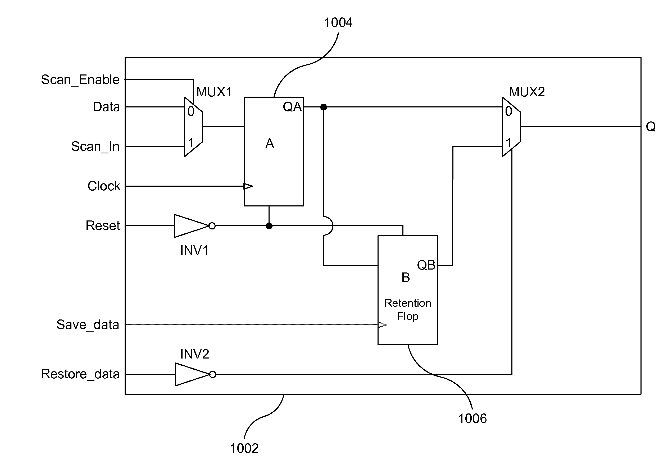
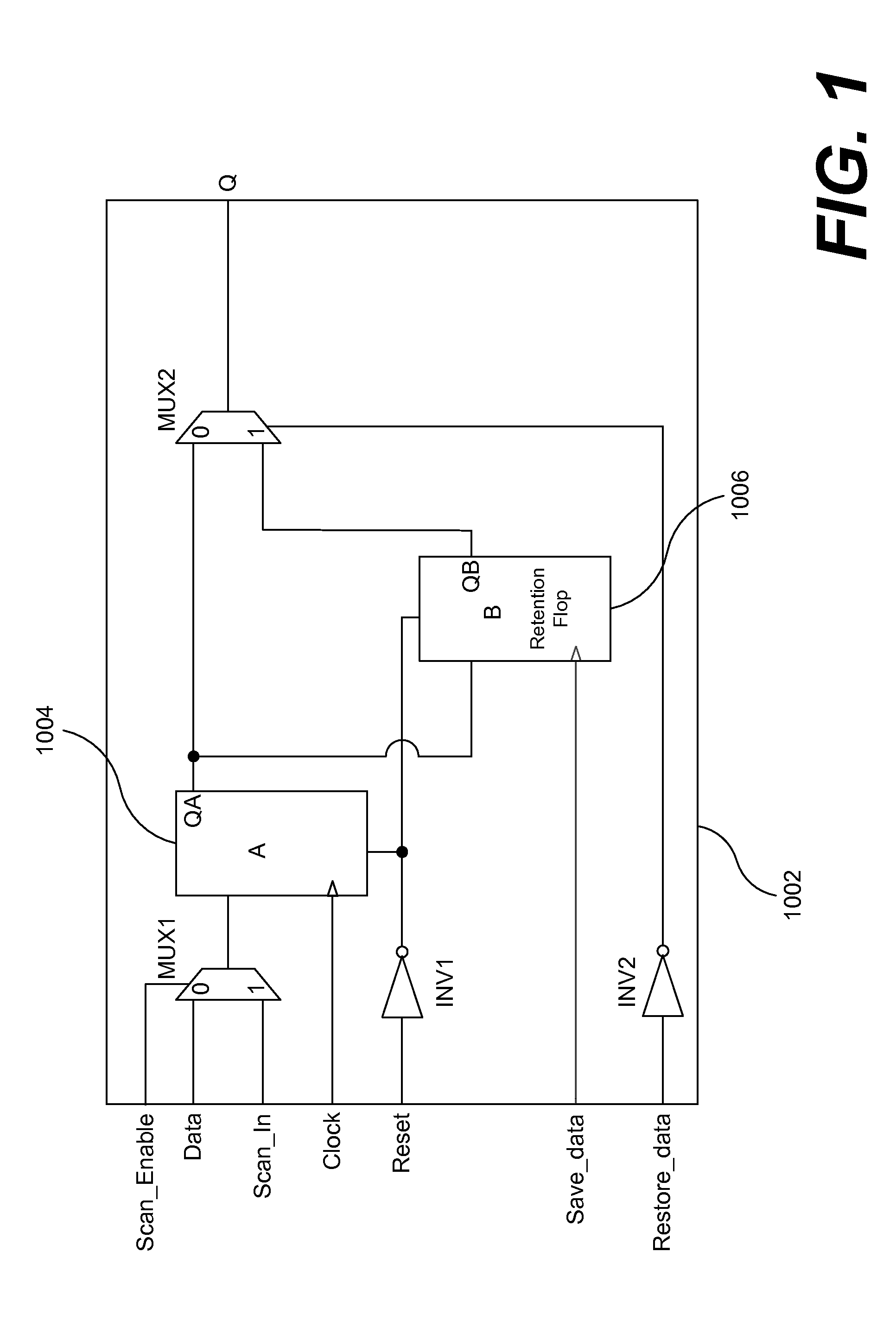
[0023]FIG. 1 shows an exemplary state retention cell (or SRPG cell) 1002 that includes two flip-flops or “flops” (functional flop A 1004 and retention flop B 1006), two multiplexors (MUX1 and MUX2), and two inverters (INV1 and INV2). Multiplexor MUX1 controls whether Flop A gets data from the functional path (through pin Data) or from the previous flop in the scan chain (through pin Scan_In). When pin Scan_Enable is at logic-0 value, Flop A is on the functional path (Data-Q) and when Scan_Enable is at logic-1 value Flop A is on the scan path (Scan_In-Q). The Restore_data pin would typically be at logic-1 unless the value in Flop B needs to be made visible outside the retention cell.

[0024]Flop B 1006 is the retention flop (or retention element) and is intended to hold state when the main power supply to the retention cell is shut off. Once Flop A 1004 is loaded with an initial state either through the functional pin Data or through the scan pin Scan_In, the Save_data pin is pulsed to...


PUM


Abstract

A method of testing an Integrated Circuit (IC) includes: loading a sequence of data into a chain of circuit elements that hold data values, where outputs of at least some circuit elements are connected to inputs of adjacent circuit elements so values move sequentially through the chain between a chain input for loading values and a chain output for unloading values, and a first circuit element includes a retention element for saving values during power variations related to the IC. The method further includes: saving a value from the data sequence in the retention element; and accessing the retention element for verifying an accuracy of the saved value from the data sequence.

Description

BACKGROUND OF THE INVENTION[0001]1. Field of Invention[0002]The present invention relates to integrated circuits (ICs) generally and more particularly to low-power IC systems.[0003]2. Description of Related Art[0004]IC Designs with multiple power domains are becoming increasingly common since power consumption can be reduced by temporarily powering off regions of the chip (called domains) that do not need to be active. Such designs have one or more switchable power domains and these domains can be powered off to eliminate both static and dynamic power dissipation in them. In order to ensure that the domain powers back on into a known state, switchable domains may include state retention cells (e.g., circuit elements that include retention elements for saving state values during power variations). Typically, state retention cells contain special flops or latches to retain the state of the cell when its main power supply is shut off. See, for example, U.S. Pat. Nos. 6,775,180, 7,091,7...

Claims


Application Information

Patent Timeline
IPC IPC(8): G01R31/317
CPCG01R31/318575
Inventor CHAKRAVADHANULA, KRISHNAGALLAGHER, PATRICKCHICKERMANE, VIVEKGREGOR, STEVEN L.ARORA, PUNEET
Owner CADENCE DESIGN SYST INC
Why Eureka
Try Eureka