Unidirectional multi-use proxy re-signature process

a multi-use, proxy technology, applied in the direction of user identity/authority verification, digital transmission, encryption apparatus with shift register/memory, etc., can solve the problems of limiting the utility of various applications, inefficient original proxy re-signature scheme, and unsuitable for many practical applications

Inactive Publication Date: 2009-12-31
MICROSOFT TECH LICENSING LLC
View PDF15 Cites 46 Cited by
  • Summary
  • Abstract
  • Description
  • Claims
  • Application Information

AI Technical Summary

Benefits of technology

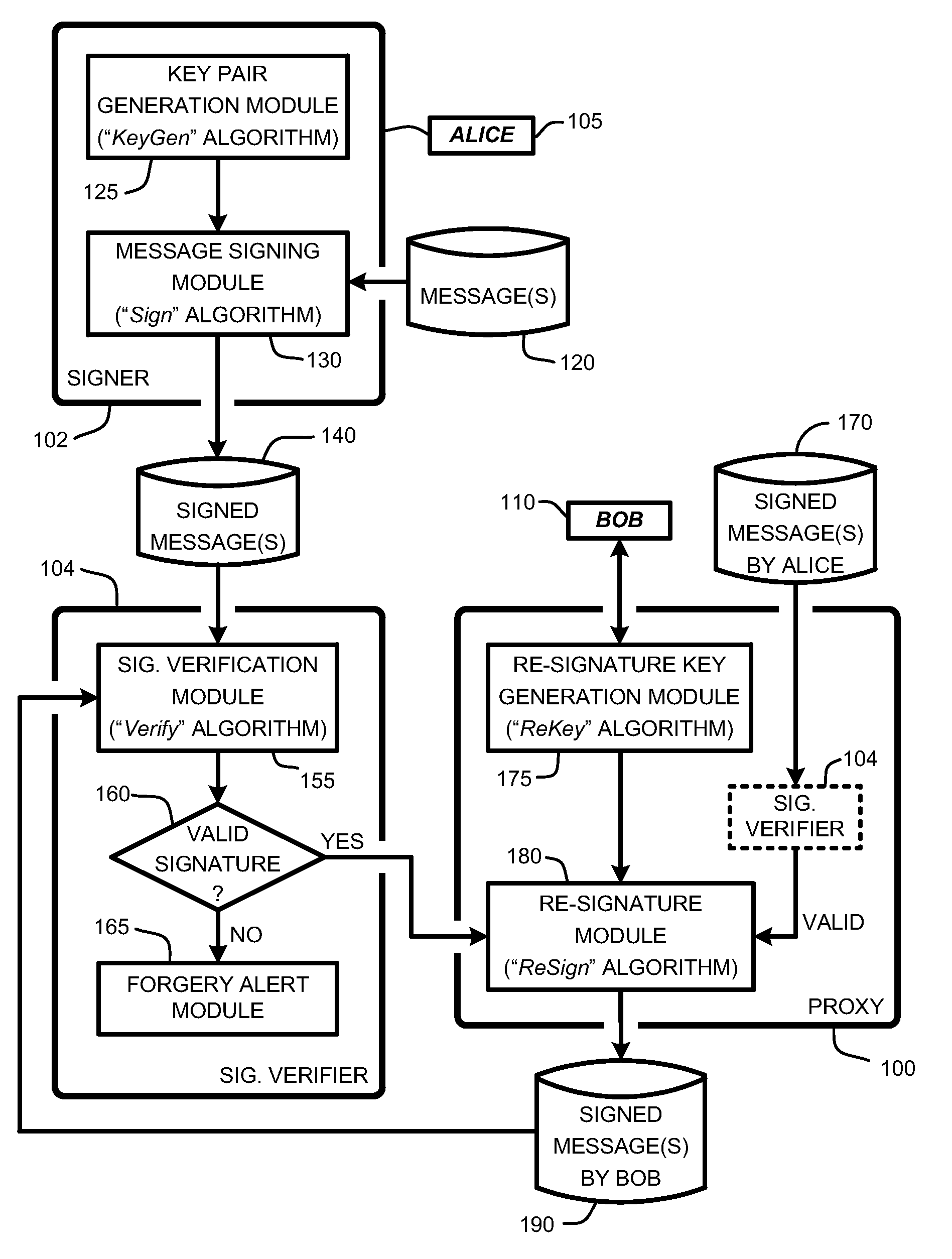
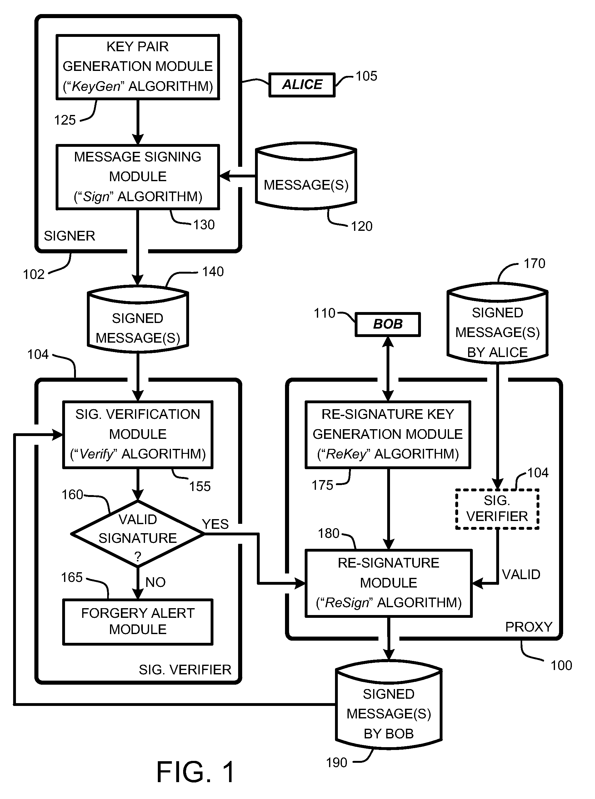
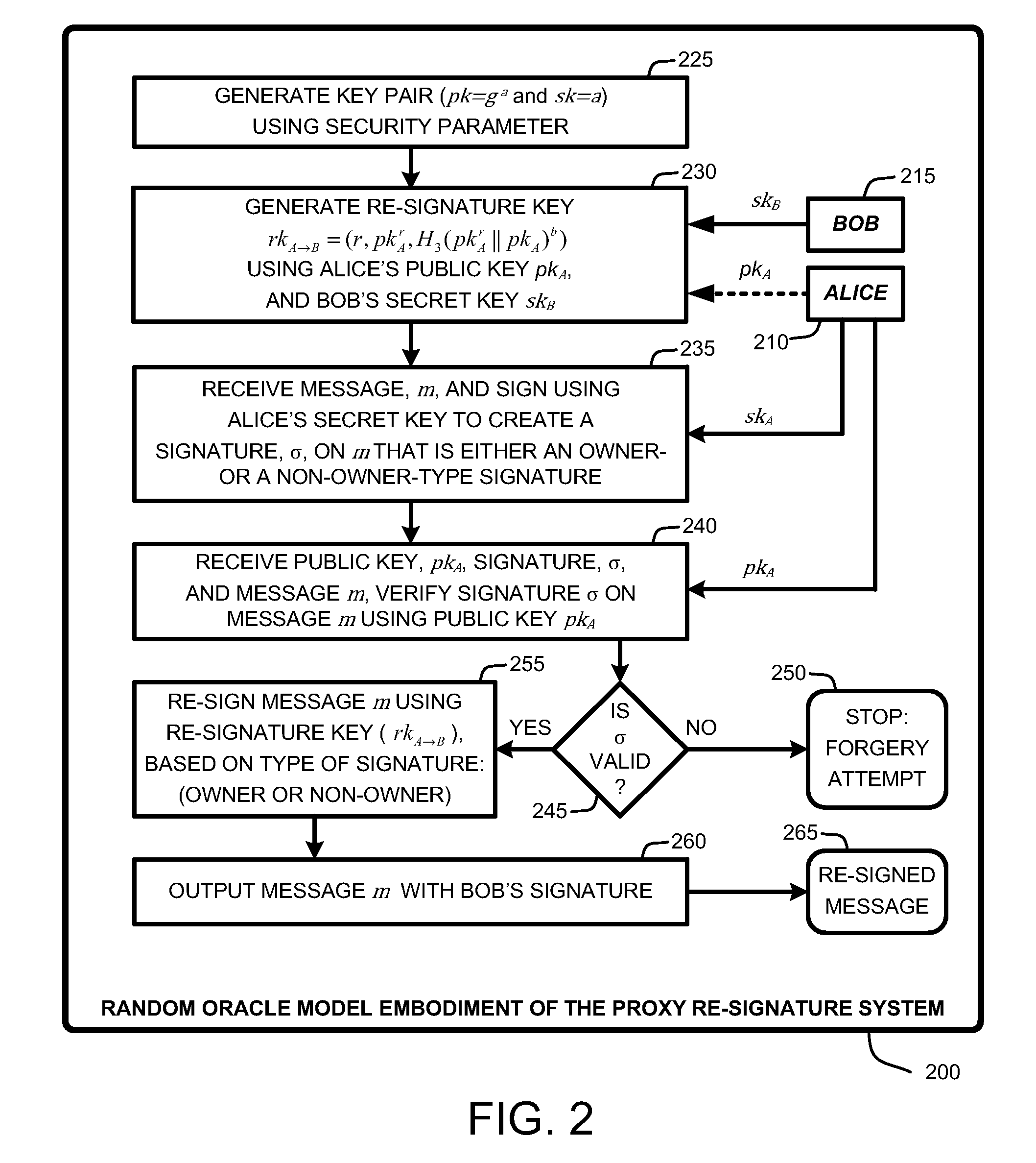
[0027]In view of the above summary, it is clear that the proxy re-signature system described herein provides various unique techniques for automatically and securely re-signing messages by transforming the signature of a delegatee to that of a delegator using collusion resistant re-signature processes. In addition to the just described benefits, other advantages of the proxy re-signature system will become apparent from the detailed description that follows hereinafter when taken in conjunction with the accompanying drawing figures.

Problems solved by technology

However, for purposes of security, conventional proxy re-signature techniques ensure that the proxy does not actually learn the signing key of either Alice or Bob during the re-signature process, and cannot sign arbitrary messages on behalf of either Alice or Bob.
Unfortunately, this original proxy re-signature scheme is considered to be inefficient, and, as such, it is generally considered to be unsuitable for many practical applications.
However, these proxy re-signature have several disadvantages that generally limit their utility for various applications.
For example, typical proxy re-signature schemes are not proven to be secure, unidirectional, and private.
One proxy re-signature scheme is proven secure and unidirectional, but it is of public proxy.
Unfortunately, many applications such as contract signing protocols require the underlying proxy re-signature scheme to be a private proxy.
Further, none of the aforementioned proxy re-signature schemes is both unidirectional and multi-use simultaneously.
Unfortunately, applications such as the proof of a taken path mentioned require the underlying proxy re-signature scheme to be simultaneously unidirectional and multi-use.

Method used


Image

  • Unidirectional multi-use proxy re-signature process
  • Unidirectional multi-use proxy re-signature process
  • Unidirectional multi-use proxy re-signature process

Examples


Embodiment Construction

[0034]In the following description of the embodiments of the claimed subject matter, reference is made to the accompanying drawings, which form a part hereof, and in which is shown by way of illustration specific embodiments in which the claimed subject matter may be practiced. It should be understood that other embodiments may be utilized and structural changes may be made without departing from the scope of the presently claimed subject matter.

1.0 Introduction

[0035]The first known proxy re-signature scheme in was introduced 1998, and was a bidirectional, multi-use, and public proxy scheme. The definition for security in proxy re-signature schemes was first formalized in a well known publication in 2005 entitled “Proxy re-signatures: new definitions, algorithms, and applications,” by G. Ateniese, S. and Hohenberger, in Proceedings of the 12th ACM Conference on Computer and Communications Security (Alexandria, Va., Nov. 7-11, 2005), ACM CCS 2005, pages 310-319.

[0036]In general, Aten...


PUM


Abstract

A “proxy re-signature system” provides various techniques for transforming a delegatee's signature on a message m into a delegator's on the same message m. Various embodiments of non-interactive re-signature generation processes are described. Various embodiments to aggregate part of signatures to reduce the size of re-signed signatures are also described. Various combinations of the proxy re-signature process and the re-signature conversion process result in an overall process that is unidirectional, multi-use, private, and non-interactive. As such, the proxy re-signature system is applicable for use with a wide range of applications.

Description

BACKGROUND[0001]1. Technical Field[0002]A “proxy re-signature system” provides a mechanism that allows secure proxy re-signatures, and in particular, various techniques for enabling secure, multi-use, unidirectional, and private proxy re-signatures in combination with various techniques for converting any secure proxy re-signature into one that is collusion-resistant with flexible temporary delegations without the need to involve a trusted third party.[0003]2. Related Art[0004]Conventionally, “proxy re-signature” techniques, as are well known to those skilled in the art, involve a cryptography technique in which a semi-trusted proxy acts as a translator between a delegatee (typically referred to as “Alice” or simply as “A”) and a delegator (typically referred to as “Bob” or simply as “B”). Such techniques are used to convert a signature (i.e., a “signing key”) from A into a signature from B on the same message.[0005]However, for purposes of security, conventional proxy re-signature ...

Claims


Application Information

Patent Timeline
Patent Type & Authority Applications(United States)
IPC IPC(8): H04L9/06
CPCH04L9/0891H04L2209/76H04L9/3247
Inventor FENG, MINZHU, BIN BENJAMINSHAO, JUN
Owner MICROSOFT TECH LICENSING LLC
Why Eureka
Try Eureka