
Firearm having a debris shield

a technology of debris shield and firearm, which is applied in the field of firearms, can solve the problems of increasing the possibility of cover plate and/or bolt assembly failure, firearm type is still susceptible to and the possibility of firearm jamming or failing, so as to reduce frictional wear and reduce the effect of fouling of firing components

Active Publication Date: 2010-01-07
ADCOR INDS
View PDF98 Cites 18 Cited by
  • Summary
  • Abstract
  • Description
  • Claims
  • Application Information

AI Technical Summary

Benefits of technology

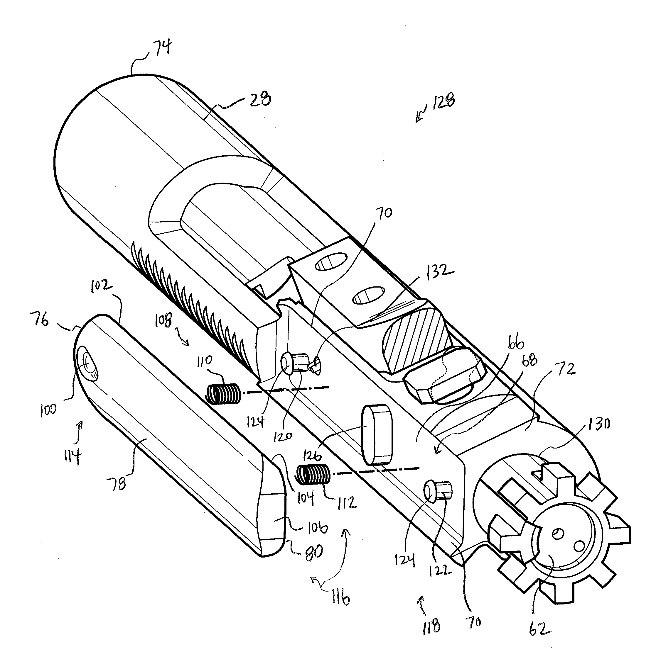
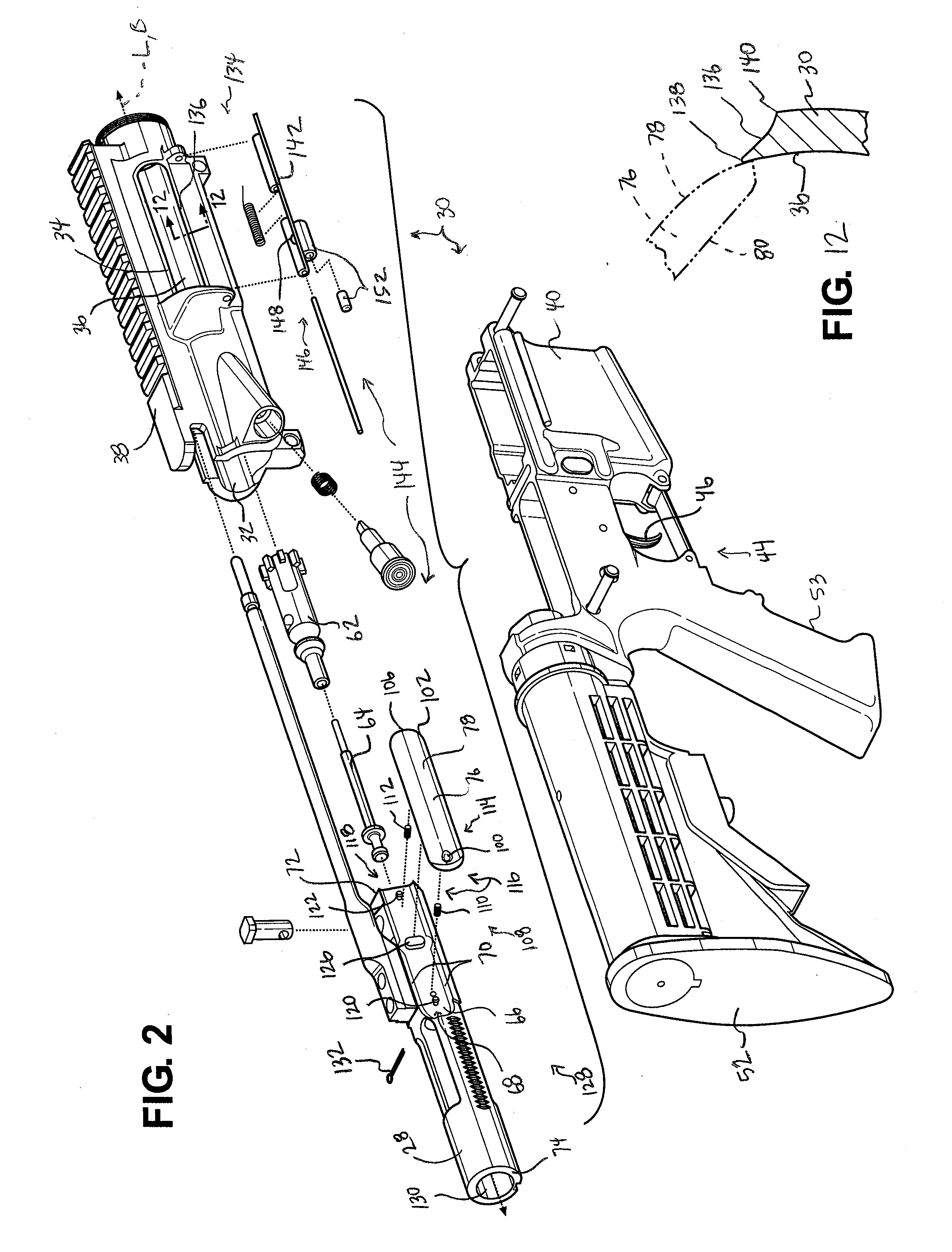
[0014]Additionally, the present invention provides for an ejection system for the firearm having the receiver defining the bore along the longitudinal axis and the ejection port transverse to the longitudinal axis. The system further includes the bolt carrier disposed in the bore and moveable relative to the receiver along the longitudinal axis between the firing position and the rearward position. A door is coupled to the receiver adjacent the ejection port with the door movable between a closed position covering the ejection port and a released position allowing the door to move away from the ejection port. The shield is coupled to the bolt carrier and movable with the bolt carrier between the firing and rearward positions with the shield blocking the ejection port when in the firing position and the shield spaced from the ejection port when in the rearward position. The system also includes a release mechanism having a first portion coupled to the shield and a second portion coupled to the door with the first portion engaging the second portion as the shield moves from the firing position to the rearward position for moving the door from the closed position to the released position.
[0015]Accordingly, the present invention defines a mechanism, in the form of a shield or a shield apparatus that minimizes, if not eliminates, fouling of the firing components, i.e. the action. In particular, the shield is longitudinally affixed to a bolt carrier to provide automatic blocking of an ejection port anytime the bolt carrier is in a firing position without having to manually close a door for preventing debris from entering the ejection port and fouling the firing components. In addition, the shield is longitudinally affixed to the bolt carrier and movable with the bolt carrier as a unit along a longitudinal axis for reducing frictional wear between the shield and the bolt carrier.

Problems solved by technology

However, this type of firearm is still susceptible to fouling of the firing components due to debris entering through the ejection port.
Accordingly, during stressful situations, such as a military situation, it is unlikely the user will consistently close the ejection port door after firing or charging the firearm, thereby allowing debris to foul the firing components and potentially cause the firearm to jam or fail.
Having the cover plate and the bolt assembly moving independently of each other in such a manner increases frictional wear between the components and thus increases the possibility of the cover plate and / or the bolt assembly failing.

Method used


Image

  • Firearm having a debris shield
  • Firearm having a debris shield
  • Firearm having a debris shield

Examples


Embodiment Construction

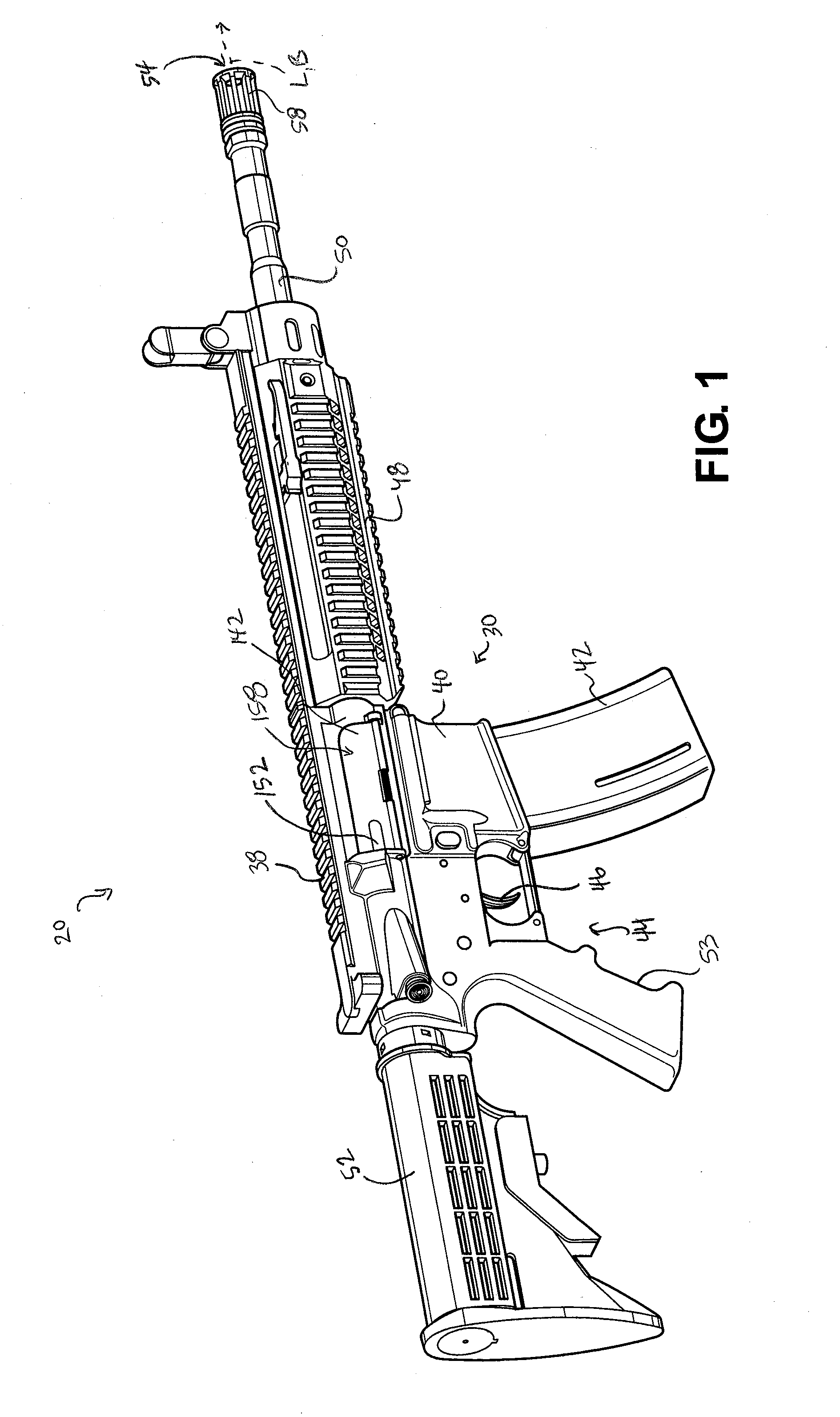
[0034]Referring to the Figures, wherein like numerals indicate like or corresponding parts throughout the several views, a firearm 20 is generally shown in FIG. 1. Also referring to FIGS. 2, 3A and 3B, the firearm 20 receives and fires a live round 22 of ammunition (hereinafter “live round”), also referred to as a cartridge, which includes a casing 24, a bullet 26, and other components to propel the bullet 26 as known to those skilled in the art.

[0035]The firearm 20 can be of a certain class of firearms 20 that utilize a direct gas impingement system or an indirect gas impingement system to eject a spent casing 24 after firing the firearm 20. Examples of such types of firearms 20 include the M16, the M4®, such as the M4® carbine, and the AR-15®, such as the AR-15® Platform. However, it should be appreciated that the firearm 20 can be of any type without departing from the nature of the present invention. The firearm 20 described herein is designed to permit easy retro-fitting of the...


PUM


Abstract

The present invention provides for a firearm having a receiver defining a bore with the receiver extending along a longitudinal axis. The receiver defines an ejection port transverse to the longitudinal axis with the bore defining an inner surface. The firearm further includes a bolt carrier disposed in the bore and moveable relative to the receiver along the longitudinal axis between a firing position and a rearward position. The firearm also includes a shield longitudinally affixed to the bolt carrier and movable with the bolt carrier as a unit between the firing and rearward positions along the longitudinal axis with the shield blocking the ejection port when in the firing position and the shield sliding along the inner surface away from the ejection port when moving to the rearward position in conjunction with the bolt carrier.

Description

CROSS REFERENCE TO RELATED APPLICATIONS[0001]The subject patent application claims priority to and the benefits of U.S. Provisional Patent Application Ser. No. 61 / 133,624, filed on Jul. 1, 2008 and U.S. Provisional Patent Application Ser. No. 61 / 211,228, filed on Mar. 27, 2009.BACKGROUND OF THE INVENTION[0002]1. Field of the Invention[0003]The subject invention relates to firearms and more specifically to mechanisms that minimize fouling of firing components.[0004]2. Description of the Prior Art[0005]Firearms typically include a receiver that houses several working components of the firearm, including firing components, with a barrel extending from the receiver. There are various classes of firearms that operate in different manners. One class of firearm utilizes a bolt carrier is disposed in the receiver that is moveable between a firing position, from which a live round of ammunition can be fired, and a retracted position, from which a spent casing is ejected. The movement of the ...

Claims


Application Information

Patent Timeline
IPC IPC(8): F41A35/02
CPCF41A3/66F41A5/18F41A5/26F41G1/02F41C23/16F41A3/12F41A35/00F41A5/28
Inventor BROWN, MICHAEL J.
Owner ADCOR INDS
Learn More