Managing low pressure turbine maximum speed in a turbofan engine

a technology of turbofan engine and maximum speed, which is applied in the direction of engine control, machines/engines, jet propulsion plants, etc., can solve the problems of limiting the ability to operate the engine, increasing the weight of the engine, and increasing the cost of the engine, so as to reduce the exit area of the nozzle

Active Publication Date: 2010-01-07
RAYTHEON TECH CORP
View PDF15 Cites 17 Cited by
  • Summary
  • Abstract
  • Description
  • Claims
  • Application Information

AI Technical Summary

Benefits of technology

[0006]A turbofan engine control system for managing a low pressure turbine speed is provided. The turbofan engine control system includes a low spool having a low pressure turbine that are housed in a core nacelle. The low pressure turbine is adapted to rotate at a speed and includes a maximum design speed. A turbofan is coupled to the low spool. A fan nacelle surroun

Problems solved by technology

The engine becomes heavier and more costly as the maximum speed increases for a given turbine design.
Current commercial turbofan engines us

Method used


Image

  • Managing low pressure turbine maximum speed in a turbofan engine
  • Managing low pressure turbine maximum speed in a turbofan engine
  • Managing low pressure turbine maximum speed in a turbofan engine

Examples


Embodiment Construction

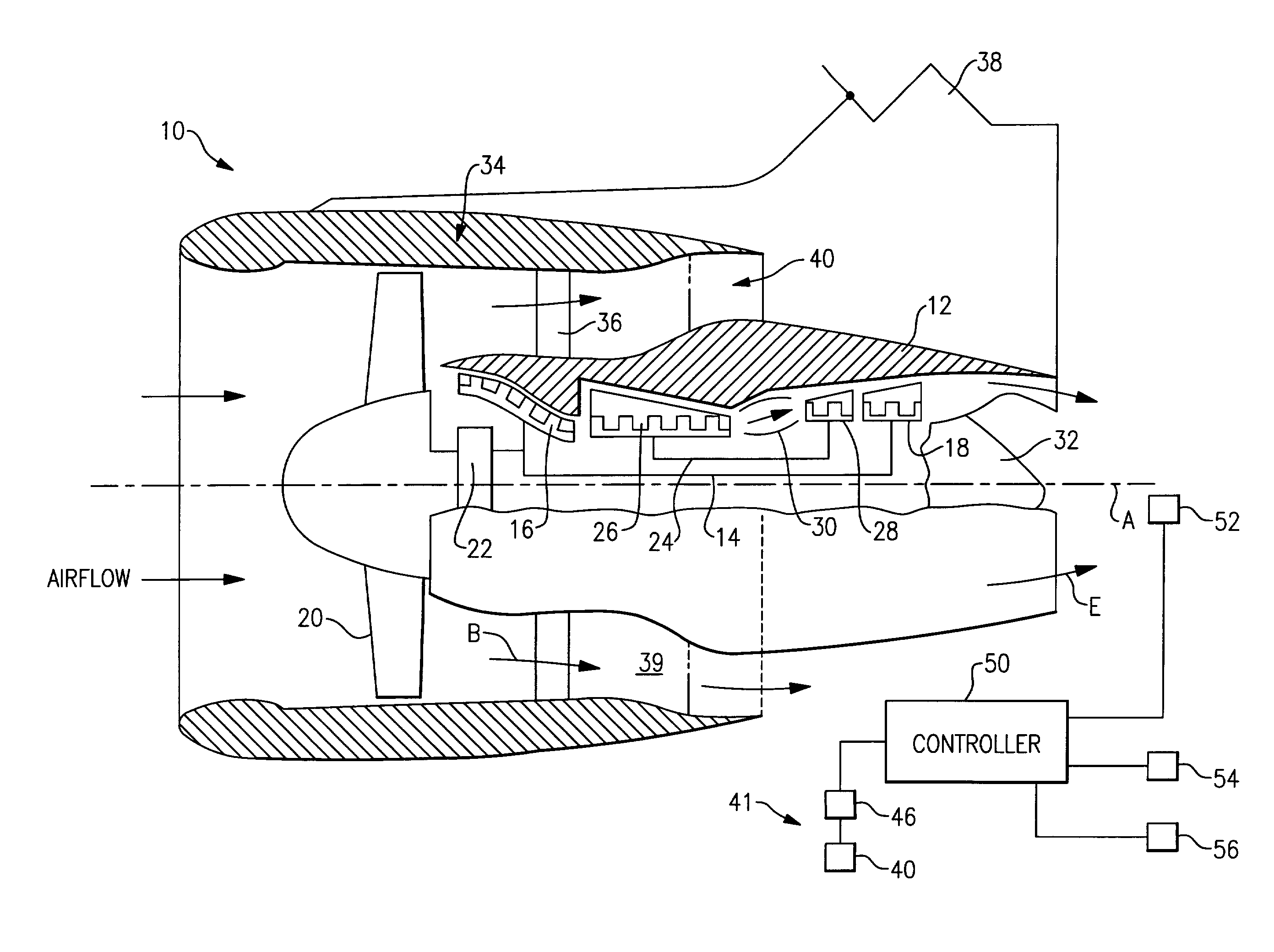
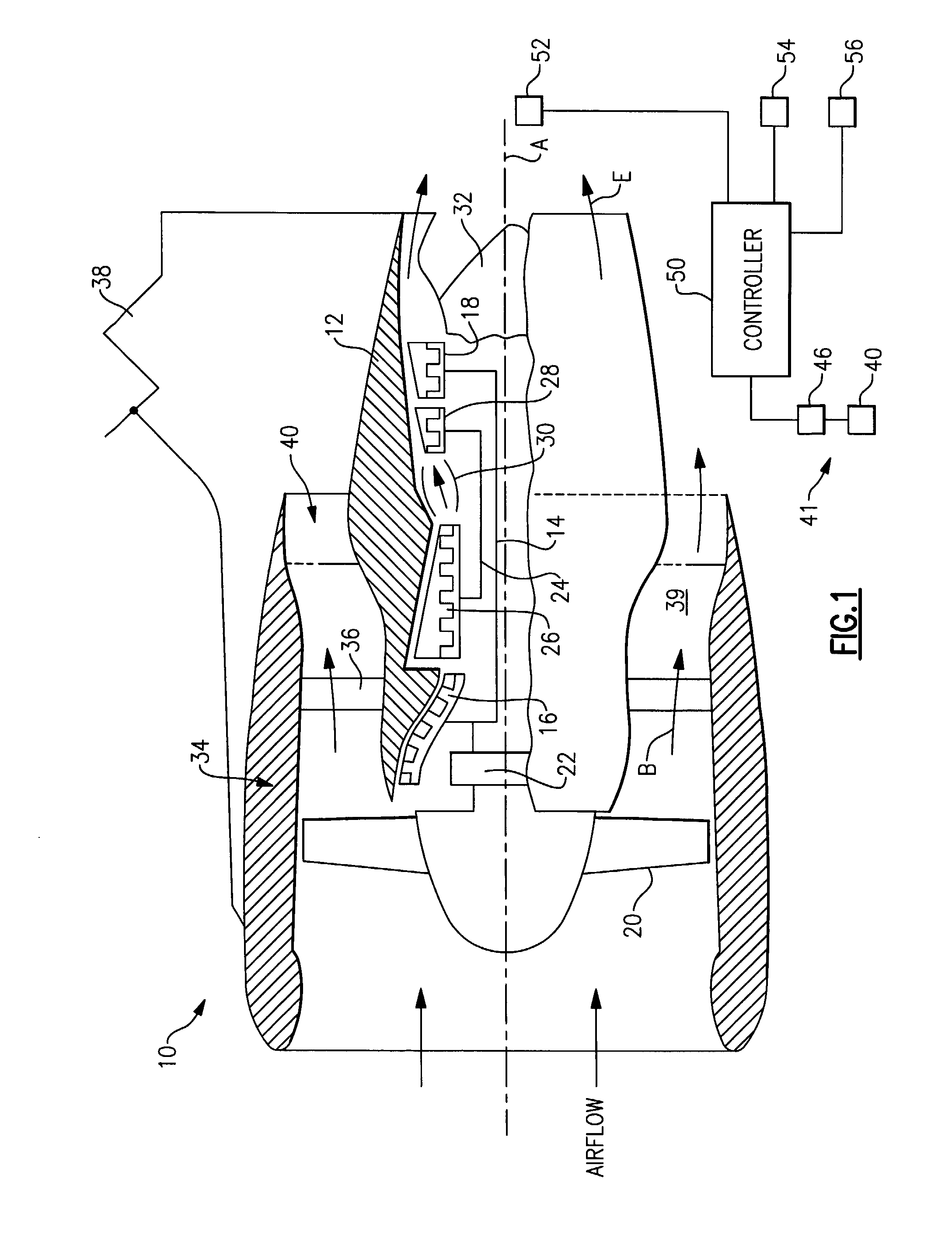
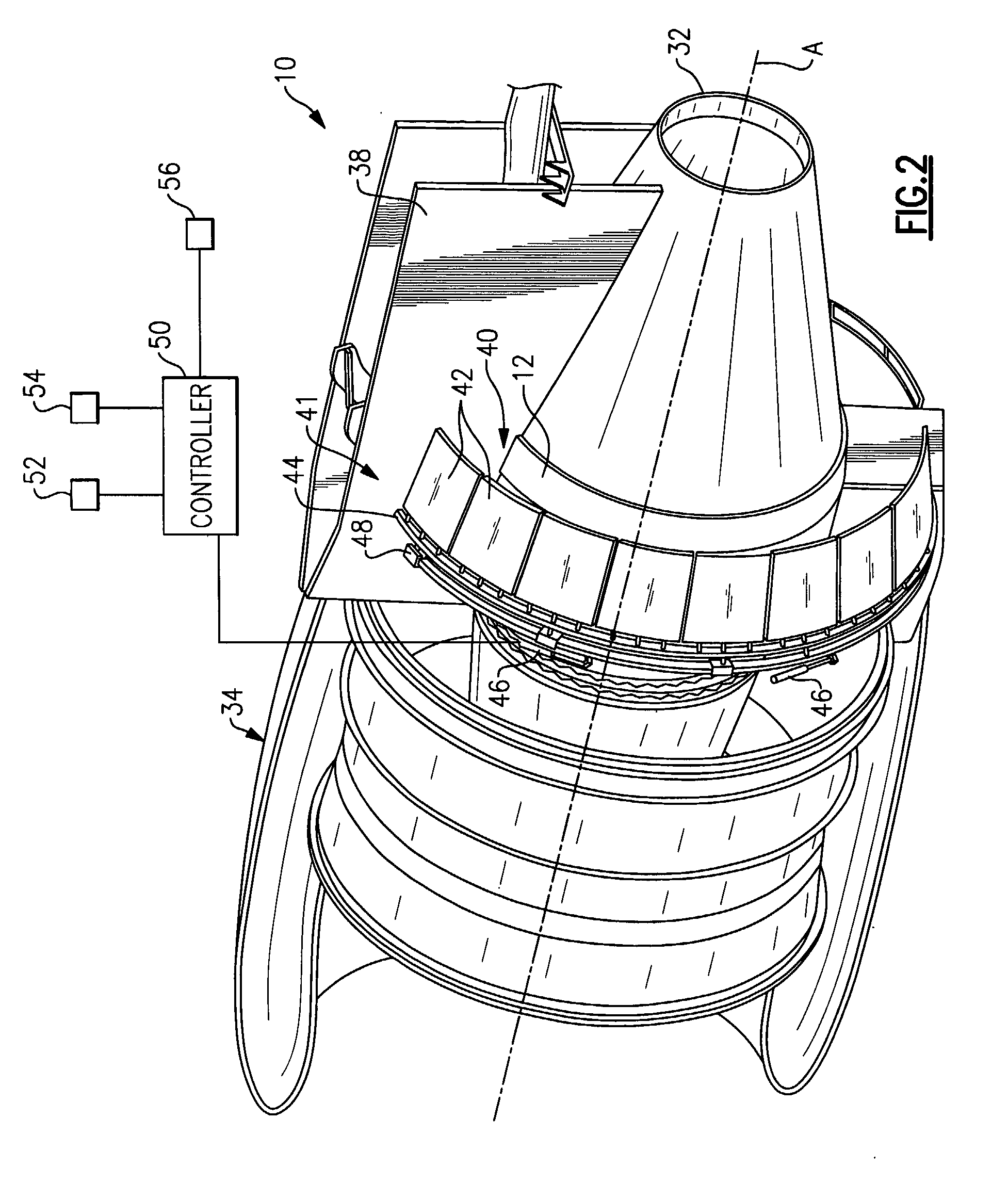
[0012]A geared turbofan engine 10 is shown in FIG. 1. A pylon 38 secures the engine 10 to an aircraft. The engine 10 includes a core nacelle 12 that houses a low spool 14 and high spool 24 rotatable about an axis A. The low spool 14 supports a low pressure compressor 16 and low pressure turbine 18. In the example, the low spool 14 drives a turbofan 20 through a gear train 22. The high spool 24 supports a high pressure compressor 26 and high pressure turbine 28. A combustor 30 is arranged between the high pressure compressor 26 and high pressure turbine 28. Compressed air from compressors 16, 26 mixes with fuel from the combustor 30 and is expanded in turbines 18, 28.

[0013]In the examples shown, the engine 10 is a high bypass turbofan arrangement. In one example, the bypass ratio is greater than 10, and the turbofan diameter is substantially larger than the diameter of the low pressure compressor 16. The low pressure turbine 18 has a pressure ratio that is greater than 5, in one exam...


PUM


Abstract

(A2) A turbofan engine control system for managing a low pressure turbine speed is provided. The turbofan engine control system includes a low spool having a low pressure turbine that are housed in a core nacelle. The low pressure turbine is adapted to rotate at a speed and includes a maximum design speed. A turbofan is coupled to the low spool. A fan nacelle surrounds the turbofan and core nacelle and provides a bypass flow path. The bypass flow path includes a nozzle exit area. A controller is programmed to command a flow control device adapted to effectively decrease the nozzle exit area in response to a condition. Reducing the nozzle exit area, either physically or otherwise, maintains the speed below the maximum design speed.

Description

BACKGROUND OF THE INVENTION[0001]This invention relates to a turbofan engine, and more particularly, the invention relates to managing the maximum speed of a low pressure turbine.[0002]A typical turbofan engine includes low and high spools. The low spool is coupled to a turbofan and typically supports a low pressure turbine and compressor. The high spool typically supports a high pressure turbine and compressor. The spools, turbines and compressors are housed in a core nacelle. The turbofan is arranged upstream from the core nacelle. A fan nacelle surrounds the turbofan and core nacelle to provide a bypass flow path having a nozzle area through which bypass flow from the turbofan exits.[0003]The turbines are designed to accommodate a maximum operating speed plus a margin. The engine becomes heavier and more costly as the maximum speed increases for a given turbine design. For example, the turbofan, low pressure turbine, low spool and fan containment system must be designed more robu...

Claims


Application Information

Patent Timeline
IPC IPC(8): F02K3/02F02C9/00
CPCF02K1/06F02K1/15F05D2270/021F05D2270/304F02K3/06
Inventor MCVEY, WILLIAM J.
Owner RAYTHEON TECH CORP
Why Eureka
Try Eureka