Image displaying apparatus

a technology for displaying apparatuses and images, applied in the direction of discharge tubes/lamp details, discharge tubes/lamp details, cathode ray tubes/electron beam tubes, etc., to achieve the effect of suppressing both halation

Inactive Publication Date: 2010-01-07
CANON KK
View PDF19 Cites 5 Cited by
  • Summary
  • Abstract
  • Description
  • Claims
  • Application Information

AI Technical Summary

Benefits of technology

[0008]The present invention has been completed in consideration of the above-described related art, and aims to provide an image displaying apparatus which simultaneously suppresses both halation and a discharging current flowing in the unlikely event of a discharge, and in which potential regulating for a spacer can be easily performed.

Problems solved by technology

Moreover, since the spacer connection wiring which extends from the resistive wiring to the top surface of the rib is provided on the side wall of the rib, it is unnecessary to provide an independent wiring to be used for the purpose of potential regulating for the spacer.

Method used


Image

  • Image displaying apparatus
  • Image displaying apparatus
  • Image displaying apparatus

Examples


first embodiment

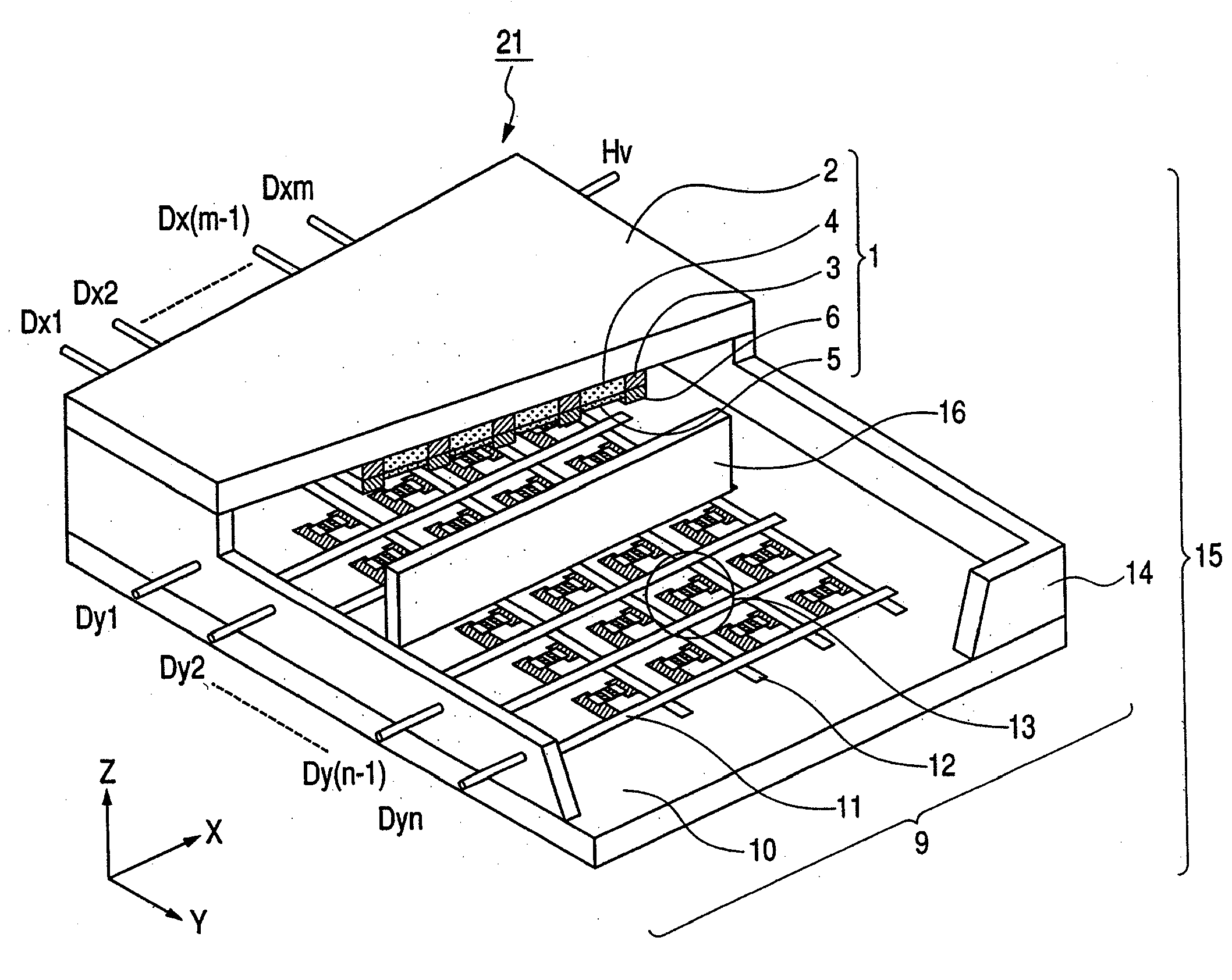
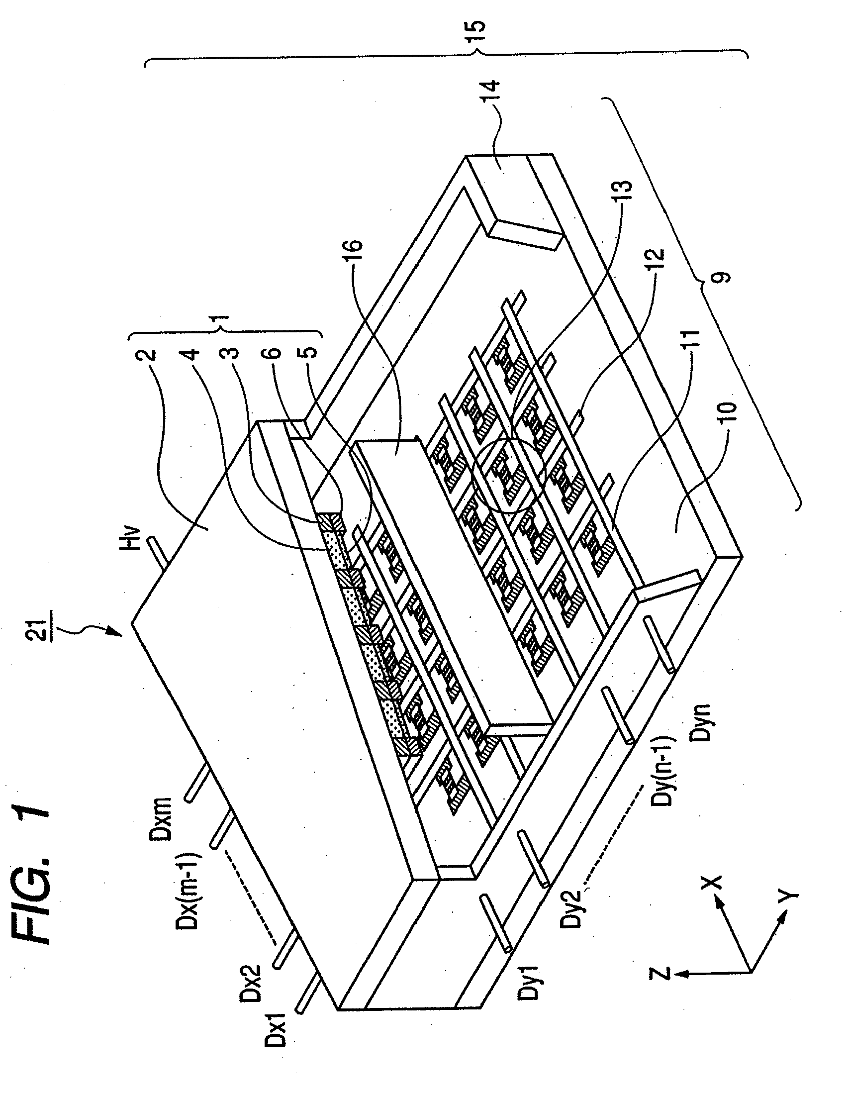
[0020]FIG. 1 is a partial fractured perspective diagram illustrating a basic structure of an image displaying apparatus according to the embodiment of the present invention. An image displaying apparatus 21 has a rear plate 9, which has two-dimensionally arranged plural surface conduction electron-emitting devices 13, and a face plate 1, which is arranged oppositely to the rear plate 9. The face plate 1 and the rear plate 9 form a vacuum envelope 15 together with an outer frame 14. A spacer 16, which is positioned between the rear plate 9 and the face plate 1 and mutually supports the rear plate 9 and the face plate 1, is provided inside the vacuum envelope 15. The space 16 is made by a high resistive member through which a small amount of current can be flowed for an antistatic purpose. In any case, the image displaying apparatus 21 is constituted by further adding a power supply, a driver circuit and the like, which are not illustrated, to the vacuum envelope 15.

[0021]The rear pla...

second embodiment

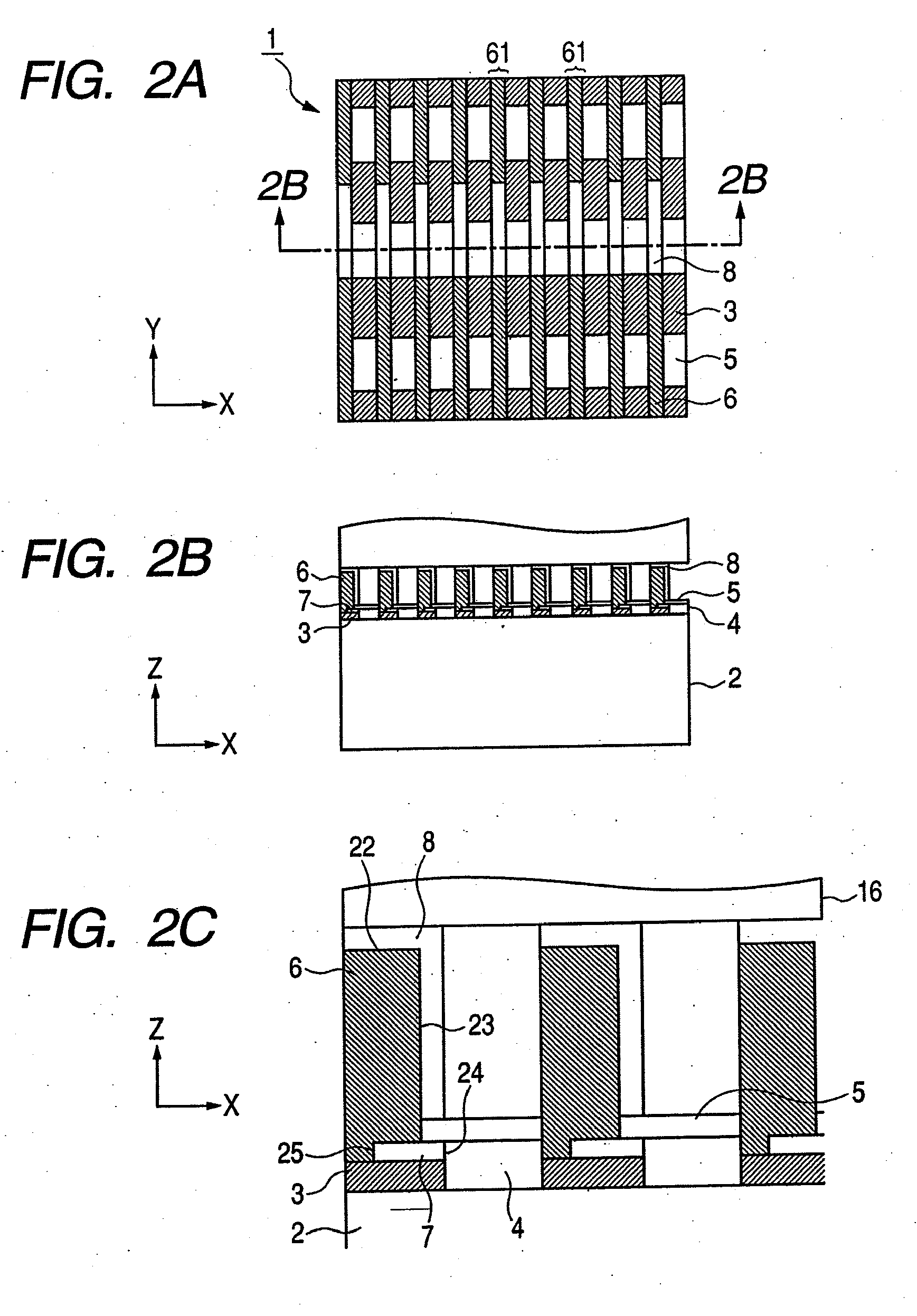
[0035]The present embodiment is substantially the same as the first embodiment except for routing of spacer connection wirings. FIGS. 3A, 3B and 3C are detailed diagrams illustrating a face plate of an image displaying apparatus according to the second embodiment. More specifically, FIG. 3A is the internal diagram of the face plate, FIG. 3B is the cross section diagram along the line 3B-3B in FIG. 3A, and FIG. 3C is the cross section diagram along the line 3C-3C in FIG. 3B. In the present embodiment, an abutment of a spacer connection wiring 8a which abuts against a spacer 16 and an abutment of the spacer connection wiring 8a which abuts against a resistive wiring (feeding wiring) 7 are respectively positioned so that they are out of alignment in the direction (Y direction) along which a first striped portion extends. That is, the spacer connection wiring 8a extends at the shortest distance between a metal back 5 and a portion of a rib 6 abutting against the spacer 16.

third embodiment

[0036]The present embodiment is characterized in that resistive wirings are regularly thinned out. FIGS. 4A, 4B and 4C are detailed diagrams illustrating a face plate of an image displaying apparatus according to the third embodiment. More specifically, FIG. 4A is the internal diagram of the face plate, FIG. 4B is the cross section diagram along the line 4B-4B in FIG. 4A, and FIG. 4C is the partial enlarged diagram of FIG. 2B. In the present embodiment, plural ribs 6 are provided, and spacer connection wirings 8b are formed alternately with the ribs 6. More specifically, the spacer connection wiring 8b is formed on both side walls 23 of the alternate rib 6 in the direction (Y direction) along which the rib 6 extends. Further, a resistive wiring (feeding wiring) 7b is provided only between the rib 6 on which the spacer connection wiring 8b has been formed and a substrate 2 (FIG. 4C). Both edge portions 24 and 25 of the resistive wiring 7b are exposed from the rib 6 in the direction (...


PUM


Abstract

To simultaneously suppress halation and discharging current flowing in the unlikely event of discharge, and easily perform potential regulating for a spacer, an image displaying apparatus comprises: a rear plate having electron-emitting devices arranged in matrix; a face plate having a substrate, light-emitting members arranged in matrix on the substrate, metal backs each covering at least one member and mutually arranged in matrix at gaps, ribs having first striped portions respectively positioned among the members and protruding toward the rear plate, and a resistive wiring including a resistor between the substrate and the ribs and electrically connecting the metal backs, and positioned oppositely to the rear plate; and a spacer positioned between the rear plate and the ribs to mutually support the rear and face plates, wherein the rib has a spacer connection wiring abutting against the spacer, and the spacer connection wiring is electrically connected to the resistive wiring.

Description

BACKGROUND OF THE INVENTION[0001]1. Field of the Invention[0002]The present invention relates to an image displaying apparatus, and, more specifically to a constitution of a face plate.[0003]2. Description of the Related Art[0004]Conventionally, an image displaying apparatus which comprises a rear plate having plural electron-emitting devices arranged two-dimensionally and a face plate having plural light-emitting members arranged two dimensionally and oppositely to the plural electron-emitting devices has been known. In the image displaying apparatus like this, the face plate and the rear plate are mutually supported generally by a spacer so as to be opposite to each other at a gap of about several millimeters. Moreover, high voltage of, e.g., approximately 10 kV is applied between the face plate and the rear plate. Consequently, a discharge occurs easily between the face plate and the rear plate, and, if the discharge once occurs, a discharging current flows into the whole of a me...

Claims


Application Information

Patent Timeline
Patent Type & Authority Applications(United States)
IPC IPC(8): H01J1/62
CPCH01J31/127H01J29/085
Inventor YAMAZAKI, KOJI
Owner CANON KK
Why Eureka
Try Eureka