Enclosure for Changing Eye Frame Designs

a technology for eye frame and design, applied in the field of eyewear, can solve the problems of less viewable space for decorative inserts, less eyeglass design and construction, and magnets severely limit the design and construction of eyeglasses, and achieve the effects of reducing the risk of eyeglasses falling off, and reducing the risk of falling o

Inactive Publication Date: 2010-01-07
ZELMAN GARY MARTIN
View PDF6 Cites 26 Cited by
  • Summary
  • Abstract
  • Description
  • Claims
  • Application Information

AI Technical Summary

Benefits of technology

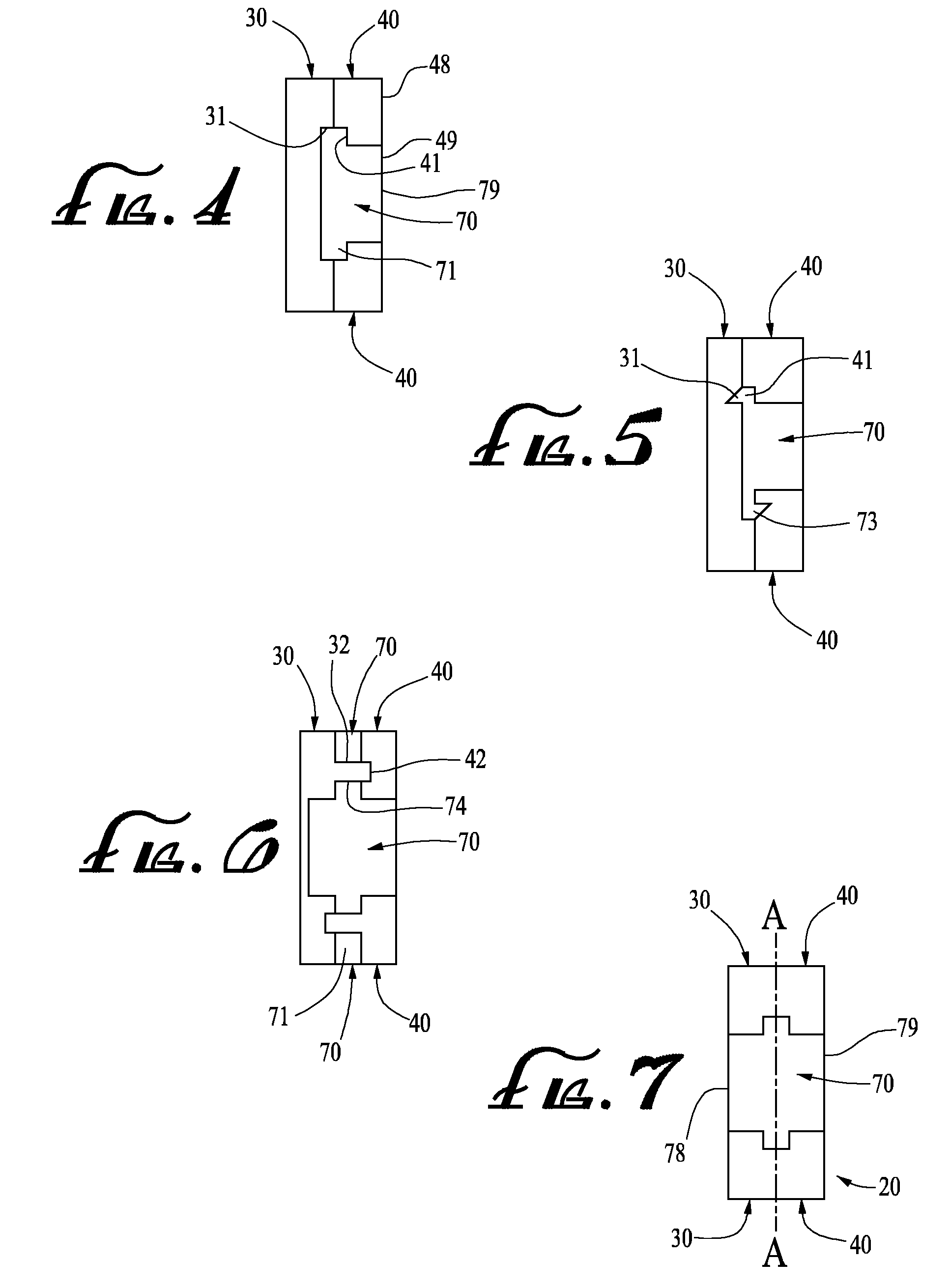
[0014]Between the two plates rests an interchangeable temple insert, depicting a decorative pattern. The temple insert can be secured by a variety of methods. In one method, described hereinafter for simplicity as a first alignment variant, the temple insert is designed with two pins protruding above and two pins protruding below the temple insert. The two plates are structured such that they contain recesses that correspond with the shape, size, and location of the pins. A alignment variant of attaching the temple insert to the plates involves shaping the pins into hooks, thus providing an extra measure of stability. A third alignment variant provides protrusions running along the length of the temple insert, both above and below the temple insert. A fourth alignment variant involves protrusions from the temple insert that contain small holes. Pins protruding from plates, structured perpendicular to the plates and the temple insert, fit through the small holes in the temple insert to offer a stronger bond. A fifth alignment variant provides that the temple insert has either reflection symmetry or rotational symmetry along the long axis of the temple frame, thereby allowing the use of both sides of the temple insert for visible decorations.
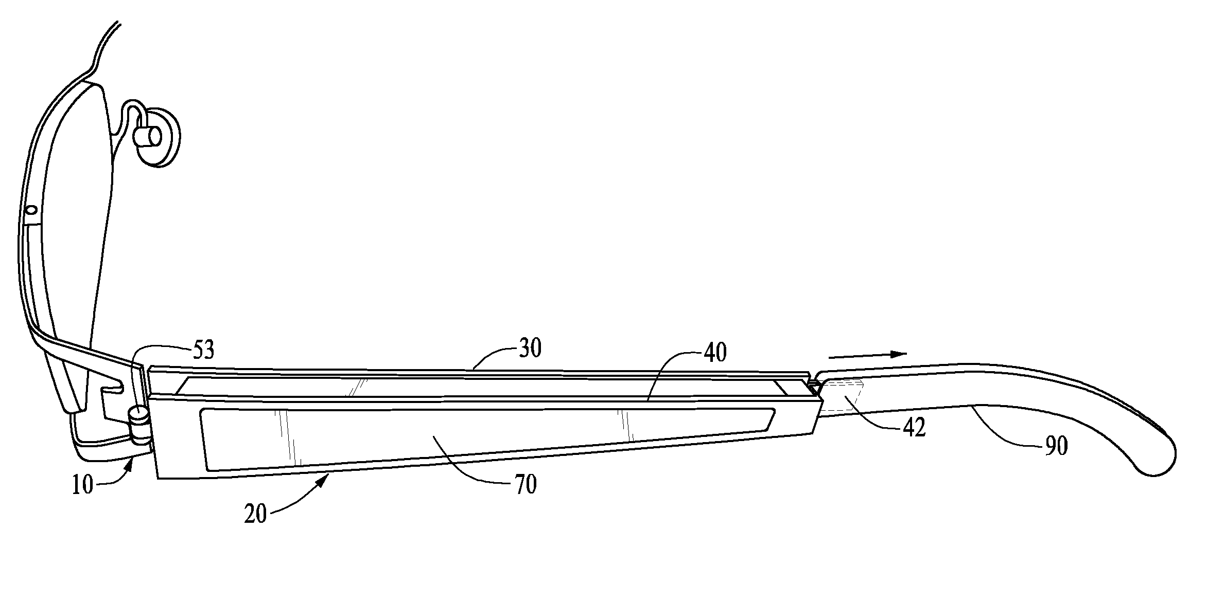
[0015]Finally, the outer plate (the plate further away from the user's head) contains a window or opening so that the interchangeable temple inserts are clearly visible from the side when the user is wearing the eyeglasses. Ideally, the temple insert should be designed such that it is flush with the outer surface of the outer plate. Not only is this more aesthetically pleasing, but it also helps hold the temple inserts in place.
[0016]In a second preferred embodiment, a converse of the first, the hinge is attached to the distal end of the plates while the attachment apparatus is placed on the proximal end. It is preferred that the outer plate be permanently fixed to the lens frame whereas the inner frame is allowed to open for replacement of the temple inserts. In this embodiment, the plates are further steadied by the eyeglass wearer during use since the wearer's head prevents the inner plate from accidental release. An obvious variation of this embodiment would be to keep the inner plate fixed while the outer plate is allowed to open. This embodiment allows for easy replacement of the temple inserts, but lacks the stability of the first variant.
[0017]In a third preferred embodiment, the hinge is attached to either the superior end (i.e., top) or inferior end (i.e., bottom) of the plates while the attachment apparatus is placed on the end opposite the hinge. It is preferred that the outer plate be permanently fixed to the lens frame whereas the inner frame is allowed to open for replacement of the temple inserts. In this embodiment, the plates are further steadied by the eyeglass wearer during use since the wearer's head prevents the inner plate from accidental release. An obvious variation of this embodiment would be to keep the inner plate fixed while the outer plate is allowed to open. This embodiment allows for easy replacement of the temple inserts, but lacks the stability of the first variant.
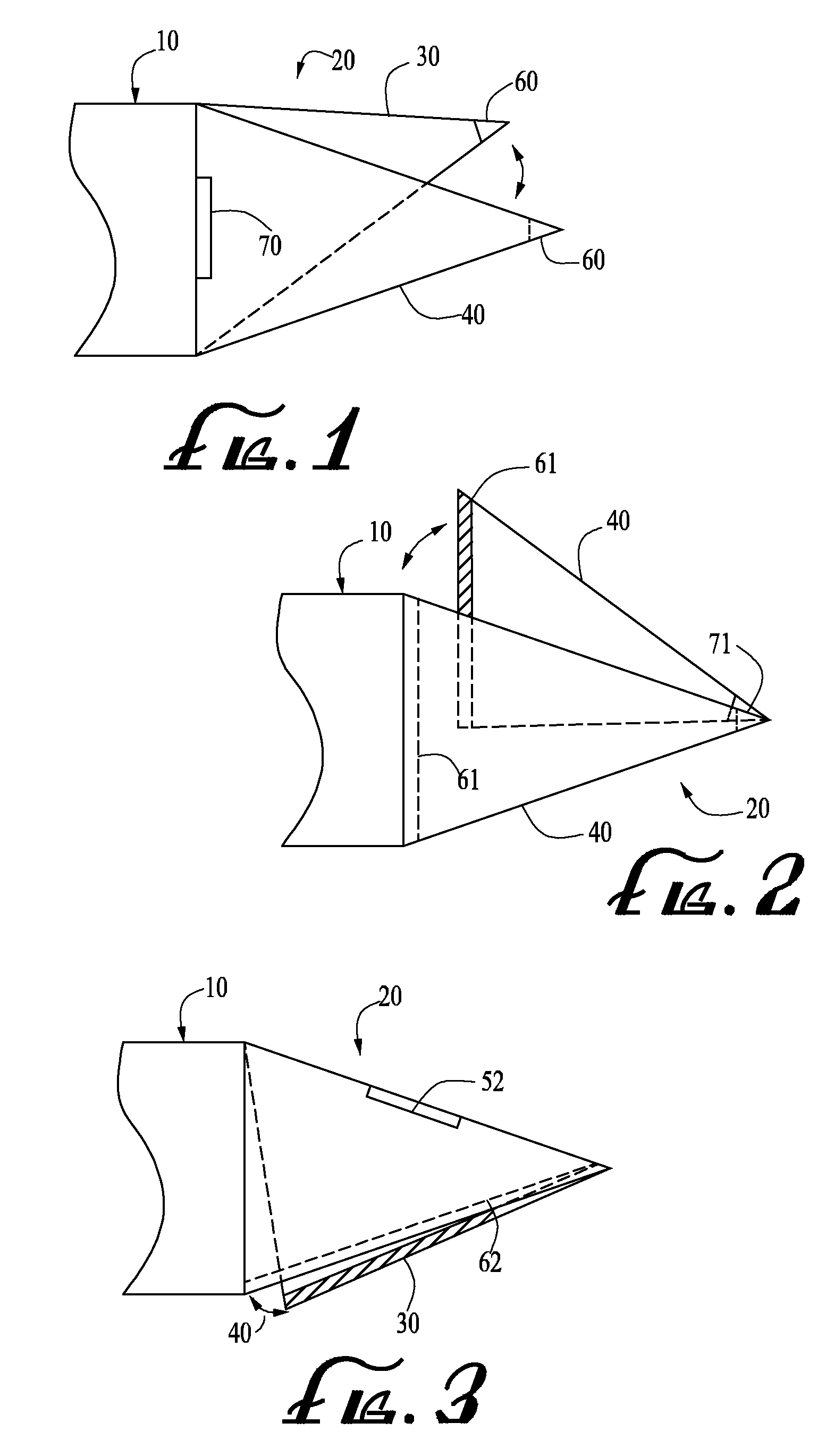
[0018]In a fourth preferred embodiment, two temple bars replace the two plates. An upper bar and a lower bar each protrude from the proximal end of the temple frame and converge at the distal end of the temple frame. The two bars and the lens frame form a triangular opening in which an interchangeable temple insert can be placed. A hinge attaches to the proximate end of one of the bars, allowing that bar to rotate outward and away from the other bar, thereby allowing easy replacement of the temple insert. An attachment apparatus located at the convergence of the two bars secures the triangle. As in the previous embodiments, the temple insert and the temple frame can be designed with recesses and protrusions to better fasten the temple insert into place.

Problems solved by technology

However, one disadvantage of securing the decorative inserts by merely using a grooved channel is that the inserts can readily slide out of the channel as easily as they can be put in.
Unfortunately, the deeper the groove, the less viewable space is available for the decorative insert.
The use of magnets severely limits the design and construction of the eyeglasses as it may be impractical or impossible to use magnetic members for certain frame designs.
Unfortunately, by requiring the use of magnetic materials, the Shapiro patent ultimately sacrifices utility and practicality.
The obvious downside of these designs is that magnetic members must be attached to each decorative insert.
As noted above, this can be impractical or impossible for some designs.
Magnets increase the cost of materials and the cost of manufacturing.
To add magnets as a component of the eyeglasses, the complexity of the manufacturing process increases significantly.

Method used


Image

  • Enclosure for Changing Eye Frame Designs
  • Enclosure for Changing Eye Frame Designs
  • Enclosure for Changing Eye Frame Designs

Examples


Embodiment Construction

[0033]The invention is for a pair of eyeglasses having temple frame designed to securely hold an interchangeable temple insert. Preferred embodiments of the present invention will now be described in detail with reference to the appended drawings, in which like elements are denoted with the same reference numerals.

[0034]FIG. 1 is an enlarged side perspective view of a lens frame and a temple frame in accordance with a first preferred embodiment of the present invention. As shown, a lens frame 10 is connected to a temple frame 20. The temple frame 20 consists of an inner plate 30, located proximate to the eyeglass wearer's head, and an outer plate 40. The inner plate 30 and the outer plate 40 are joined by a hinge 50 at an end of the temple frame 20 proximate to the lens frame 10. At the opposite end of the temple frame 20, the inner plate 30 and the outer plate 40 are joined by an attachment apparatus 60.

[0035]FIG. 2 is an enlarged side perspective view of a lens frame and a temple ...


PUM


Abstract

Eyeglasses comprising a lens frame and a pair of temple frames, to which are attached decorative temple inserts by securing two temple extensions to form an enclosure for the temple inserts. The temple extensions, which are either plates or bars, are joined at one end by a hinge and are joined at the other end by an attachment apparatus. The temple inserts have protrusions that fit with recesses within the temple extensions, thereby stabilizing the inserts within the temple frame.

Description

RELATED PATENT APPLICATION [0001]This application is a Continuation-In-Part application of application Ser. No. 12 / 167,059, filed Jul. 2, 2008.FIELD OF THE INVENTION[0002]The present invention relates to eyewear. More specifically, the invention relates to attachment of decorative temple inserts to temple frames by securing two temple extensions to form an enclosure for the temple inserts.DESCRIPTION OF THE PRIOR ART[0003]It is known in the art to attach decorative additions to a pair of eyeglasses. This has been achieved through various means, including the use of grooved channels and / or magnetic members.[0004]U.S. Pat. No. 7,261,409 B1 issued to Taber discloses a means for securing decorative inserts to a pair of eyeglasses using a grooved channel. The temple frame is designed with a channel that allows a decorative insert to be slid into the temple frame at the hinge end, the end proximal to the lens frame. The decorative insert, when attached to a temple insert, is designed to f...

Claims


Application Information

Patent Timeline
Patent Type & Authority Applications(United States)
IPC IPC(8): G02C11/02
CPCG02C2200/02G02C11/02
Inventor ZELMAN, GARY MARTIN
Owner ZELMAN GARY MARTIN
Why Eureka
Try Eureka