Optical coherence tomographic imaging apparatus and optical coherence tomographic imaging method

a tomographic imaging and optical coherence technology, applied in the field of optical coherence tomographic imaging apparatus and optical coherence tomographic imaging method, can solve the problems of limited intensity of a measuring beam in view of the influence of the retina, difficult to measure a target layer or part of the retina with high sensitivity, etc., and achieve high contrast

Inactive Publication Date: 2010-01-07
CANON KK
View PDF0 Cites 140 Cited by
  • Summary
  • Abstract
  • Description
  • Claims
  • Application Information

AI Technical Summary

Benefits of technology

[0036]According to the present invention, it is possible to realize the optical coherence tomographic imaging apparatus and the optical coherence tomographic imaging method which are capable of acquiring the tomographic image with high contrast.

Problems solved by technology

Therefore, there is a case where it is difficult to measure a target layer or part of the retina with high sensitivity.
This is because, though high-sensitive measurement may be achieved in a case where the measuring beam is substantially perpendicularly incident on the target layer of the retina, high-sensitive measurement is not achieved in a case where the measuring beam is incident on the target layer at an angle which is not substantially perpendicular.
However, in the case where the retina is to be imaged, there is a limit on the intensity of a measuring beam in view of the influence on the retina.
Thus, it is not better to increase the intensity of the measuring beam.

Method used


Image

  • Optical coherence tomographic imaging apparatus and optical coherence tomographic imaging method
  • Optical coherence tomographic imaging apparatus and optical coherence tomographic imaging method
  • Optical coherence tomographic imaging apparatus and optical coherence tomographic imaging method

Examples


example 1

[0088]In Example 1, an optical coherence tomographic imaging apparatus (OCT apparatus) to which the present invention is applied is described.

[0089]In this example, particularly, time domain OCT (TD-OCT) for acquiring a tomographic image of a retina of an eye is described.

[0090]The present invention may be applied to not only the TD-OCT but also a Fourier domain OCT (FD-OCT).

[0091]The schematic structure of the entire optical system of the OCT apparatus according to this example is described.

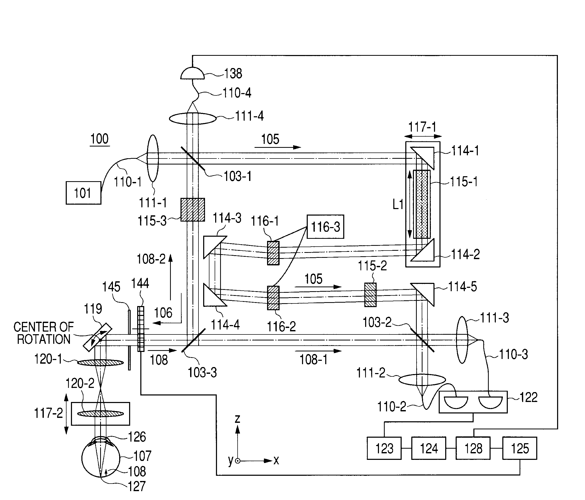
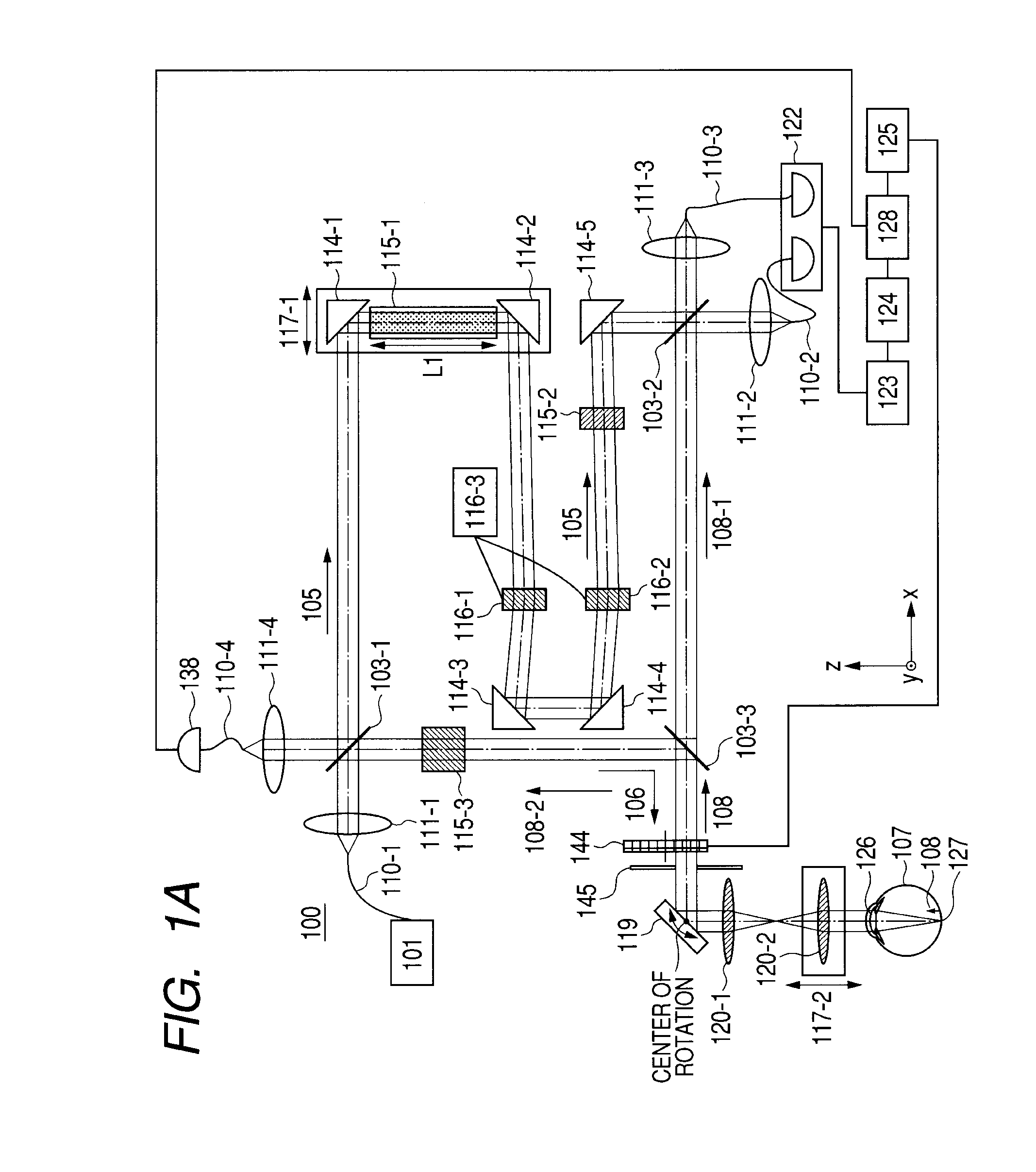
[0092]FIG. 1A is an explanatory view illustrating the schematic structure of the entire optical system of the OCT apparatus according to this example.

[0093]In FIG. 1A, an OCT apparatus 100 includes beam splitters 103-1 to 103-3, single-mode optical fibers 110-1 to 110-4, lenses 111-1 to 111-4 and 120-1 and 120-2, and reference mirrors 114-1 to 114-5. Reference numeral 105 denotes a reference beam, 106 denotes a measuring beam, 107 denotes an eye (object), and 108 denotes a return beam.

[0094]The ...

example 2

[0190]In Example 2, a structural example in which optical fibers are provided for any optical paths described in Example 1 is described.

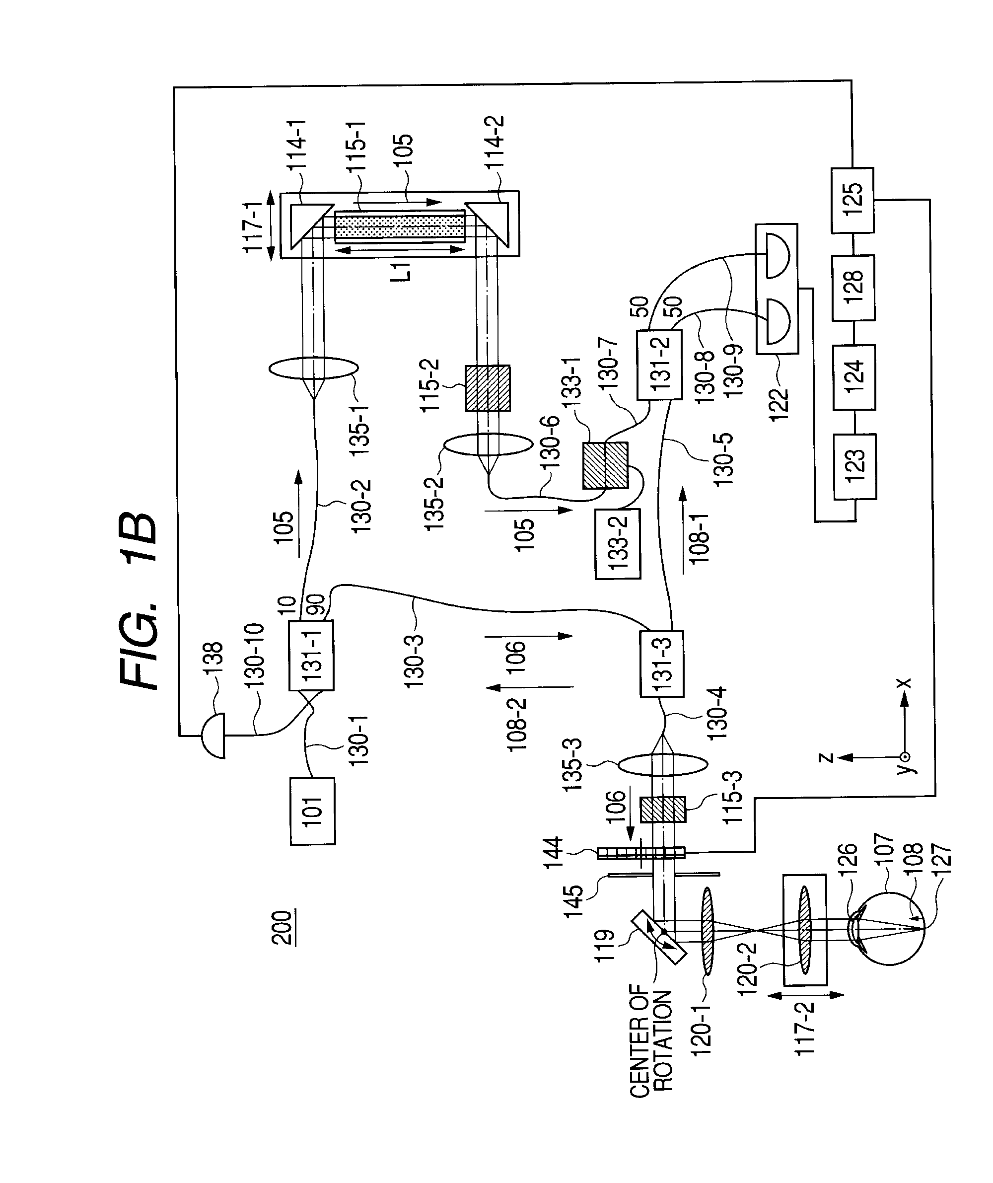
[0191]FIG. 1B is an explanatory view illustrating a schematic structure of the entire optical system of an OCT apparatus according to this example.

[0192]In FIG. 1B, constituent elements which are identical to or correspond to the constituent elements in Example 1 as described in FIG. 1A are expressed by the same reference numerals and symbols, and thus the duplicated description is omitted. In FIG. 1B, an OCT apparatus 200 includes single-mode optical fibers 130-1 to 130-10, and optical couplers 130-1 to 131-3.

[0193]In this example, the OCT apparatus 200 is used as an apparatus for acquiring a tomographic image of the retina 127 of the eye 107 to be inspected.

[0194]In this example, optical fibers are used for constructing parts of the optical system to reduce a size of the OCT apparatus. Except for the use of the optical fibers, the OCT apparatus ac...


PUM


Abstract

An optical coherence tomographic imaging apparatus which has a light intensity varying portion provided on a first optical path for guiding a measuring beam to an object for varying an intensity of the measuring beam; an illumination condition varying portion for varying an illumination condition of the measuring beam that has passed through the light intensity varying portion for the object between a first illumination condition in which a center part of the measuring beam is not blocked and a second illumination condition in which the center part of the measuring beam is blocked; and an image forming portion for weighting a first tomographic image acquired in the first illumination condition and a second tomographic image acquired in the second illumination condition and composing the weighted first second tomographic images to form a third tomographic image.

Description

BACKGROUND OF THE INVENTION[0001]1. Field of the Invention[0002]The present invention relates to an optical coherence tomographic imaging apparatus and an optical coherence tomographic imaging method, and more particularly, to an optical coherence tomographic imaging apparatus and an optical coherence tomographic imaging method which are used for ophthalmologic diagnosis and treatment.[0003]2. Description of the Related Art[0004]An optical tomographic imaging apparatus for optical coherence tomography (OCT) using multi-wavelength optical coherence (hereinafter referred to as OCT apparatus) is capable of acquiring a tomographic image of a retina at a fundus of an eye to be inspected at high resolution, and is widely used for ophthalmologic diagnosis of the retina.[0005]The OCT apparatus is an apparatus for irradiating the fundus of an eye to be inspected with a measuring beam which is a low-coherent beam to obtain interference light between backscattered light from the fundus and a r...

Claims


Application Information

Patent Timeline
Patent Type & Authority Applications(United States)
IPC IPC(8): G01B11/02
CPCA61B3/102G01N21/4795G01B9/02012G01B9/02087G01B9/02091G01B9/02034G01B9/02003
Inventor HIROSE, FUTOSHI
Owner CANON KK
Why Eureka
Try Eureka