
Image encoding apparatus and method

a technology of image encoding and encoding apparatus, which is applied in the direction of code conversion, color television with bandwidth reduction, television systems, etc., can solve the problems of difficult to achieve poor prediction of code amount variation, and non-uniform image quality within a picture, so as to maintain the uniformity of image quality

Inactive Publication Date: 2010-01-07
KOKUSA ELECTRIC CO LTD
View PDF3 Cites 14 Cited by
  • Summary
  • Abstract
  • Description
  • Claims
  • Application Information

AI Technical Summary

Benefits of technology

[0010]In view of the above, the present invention provides an image encoding apparatus and method for encoding a moving picture, which is capable of maintaining the uniformity of the image quality even though the temporal correlation of the images is low.
[0013]In accordance with the aspects of the present invention, it is possible to provide an image encoding apparatus and an image encoding method capable of maintaining the uniformity of the image quality.

Problems solved by technology

However, the variation of the quantization parameter may lead to nonuniformity in the image quality within a picture.
However, in the method of Patent Document 1, when the temporal correlation of the images is considerably low, for example, due to scene change or rapid panning of the camera, prediction of the variation in the code amount is poorly carried out and, thus, it is necessary to largely vary the quantization parameter.
Consequently, in the conventional technique, it is difficult to achieve the uniformity of the image quality when the temporal correlation of the images is considerably low.

Method used


Image

  • Image encoding apparatus and method
  • Image encoding apparatus and method
  • Image encoding apparatus and method

Examples


Embodiment Construction

[0020]Hereinafter, embodiments of the present invention will be described in detail with reference to the accompanying drawings which form a part hereof.

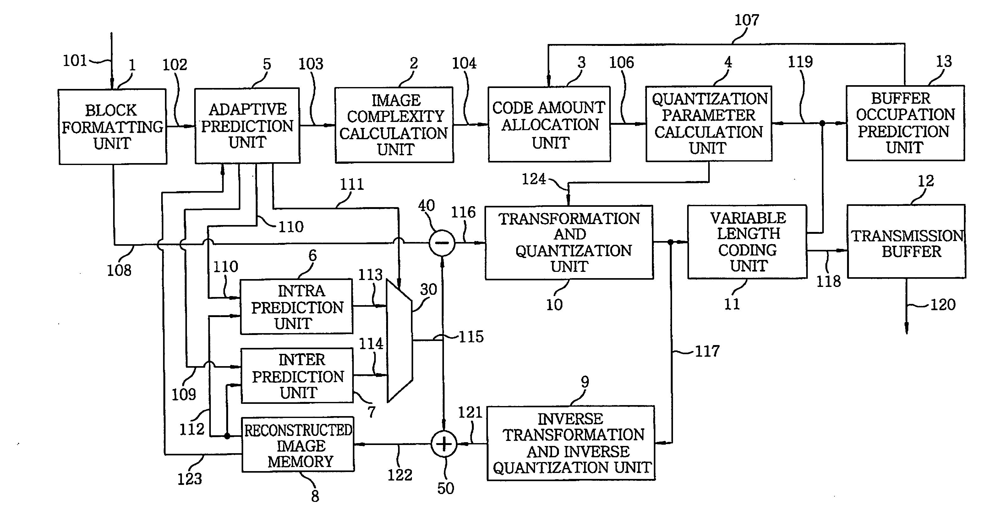
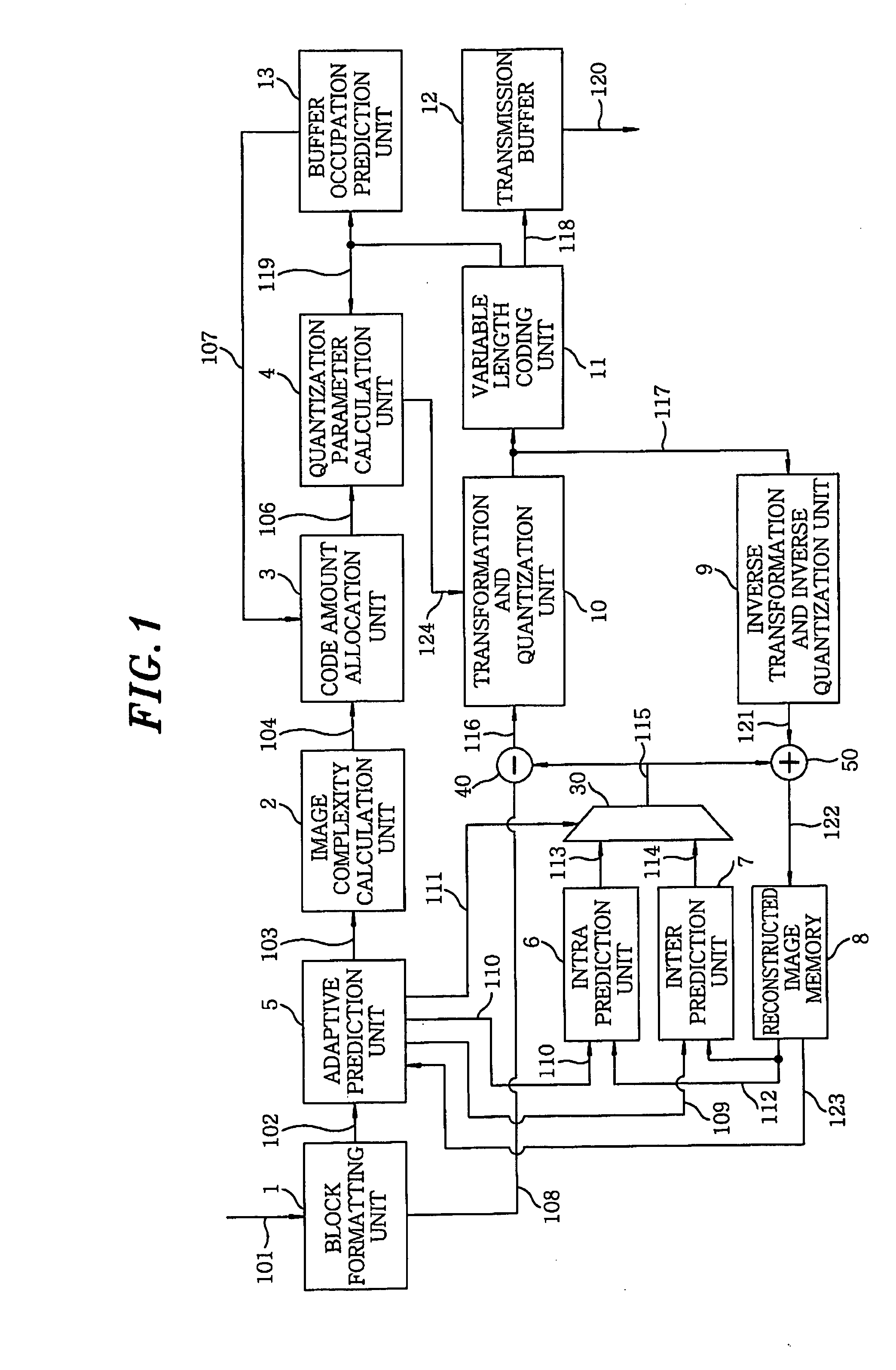
[0021]FIG. 1 is a functional block diagram of an image encoding apparatus in accordance with an embodiment of the present invention.

[0022]Referring to FIG. 1, image signals are inputted to a block formatting unit 1 via a line 101. A picture is decomposed into scanning lines to obtain image signals, which are transmitted by serial data transmission defined by, e.g., SMPTE 292M. The block formatting unit 1 is a delay circuit. The block formatting unit 1 accumulates data the amount of which corresponds to one row of macroblocks (MBs) and, then, outputs pixel data of each macroblock of 16×16 pixels to an adaptive prediction unit 5 via a line 102. Further, the block formatting unit 1 outputs the pixel data of the macroblock to a line 108 after delay until allocation of an allowable code amount to a complexity prediction region and calcul...


PUM


Abstract

An image encoding apparatus includes a calculation unit for calculating complexity from pixel values of an input image, the complexity representing a code amount generated by prediction encoding each block included in a prediction target region of the input image, and an allocation unit for allocating a code amount to each block based on the calculated complexity of each block and an allowable code amount previously set for the prediction target region. The apparatus further includes a determination unit for determining an encoding parameter corresponding to each block based on the complexity of each block and the code amount allocated to each block, and an encoding unit for encoding each block by using the determined encoding parameter of each block. Finally, the apparatus includes a resetting unit for resetting the allowable code amount for a next prediction target region based on an occupancy amount of a buffer.

Description

FIELD OF THE INVENTION[0001]The present invention relates to an image encoding apparatus and method for encoding a moving picture.BACKGROUND OF THE INVENTION[0002]In an image encoding scheme such as MPEG-2 (Moving Picture Experts Group, ISO / IEC 13818-1), H.264 (ISO / IEC 14496-10) or the like, the amount of encoded data (referred to as “code amount”, hereinafter) is varied according to complexity of an input image or an encoding method. Accordingly, an image transmission system using an image encoding technique requires a buffer for absorbing variation in the code amount to realize sequential reproduction of an encoded bit stream.[0003]In order to realize sequential reproduction with a limited buffer size, it is necessary to control variation in the code amount to prevent overflow and underflow of the buffer. The control of the code amount is realized by varying a quantization parameter. If buffer occupancy becomes larger, the quantization parameter is set to be increased, whereas if ...

Claims


Application Information

Patent Timeline
IPC IPC(8): H04N7/32H04N19/50H03M7/30H04N19/115H04N19/126H04N19/134H04N19/136H04N19/14H04N19/149H04N19/174H04N19/176H04N19/196H04N19/423H04N19/503H04N19/593H04N19/60H04N19/61H04N19/91
CPCH04N19/176H04N19/15H04N19/17H04N19/124H04N19/152H04N19/61
Inventor KONDO, MASATOSHIYAMAGUCHI, MUNEAKI
Owner KOKUSA ELECTRIC CO LTD
Learn More