
Radio transmission device and radio transmission method

a radio transmission device and radio transmission technology, applied in the field of radio transmission apparatus and radio transmission method, can solve the problems of increasing rss, shortening the number of orthogonal sequences available, and shortening the number of quasi-orthogonal sequences with low cross-correlation, so as to prevent the accuracy of channel estimation

Active Publication Date: 2010-01-07
PANASONIC INTELLECTUAL PROPERTY CORP OF AMERICA
View PDF10 Cites 44 Cited by
  • Summary
  • Abstract
  • Description
  • Claims
  • Application Information

AI Technical Summary

Benefits of technology

The present invention relates to a radio transmitting apparatus and method that use CAZAC sequences (also known as Constant Amplitude and Zadoff-Chu sequences) as reference signals for channel estimation. These sequences have good characteristics such as constant frequency response and cross-correlation characteristics. The invention proposes to use these sequences as RSs (reference signals) for uplink data transmission, where they can be multiplexed with other sequences and still maintain their performance. The invention also describes a method for detecting the correlation values of cyclic shift sequences, which can be used as orthogonal sequences. The use of these sequences as reference signals for channel estimation can improve the accuracy of data demodulation in uplink transmission.

Problems solved by technology

However, a shortage in the number of orthogonal sequences available for use in narrowband transmission or a shortage in the number of quasi-orthogonal sequences having low cross-correlation, has been raised as an issue.
As a result, the influence of interference between cells by DM-RSs increases and the accuracy of channel estimation is damaged significantly.

Method used


Image

  • Radio transmission device and radio transmission method
  • Radio transmission device and radio transmission method
  • Radio transmission device and radio transmission method

Examples


embodiment 1

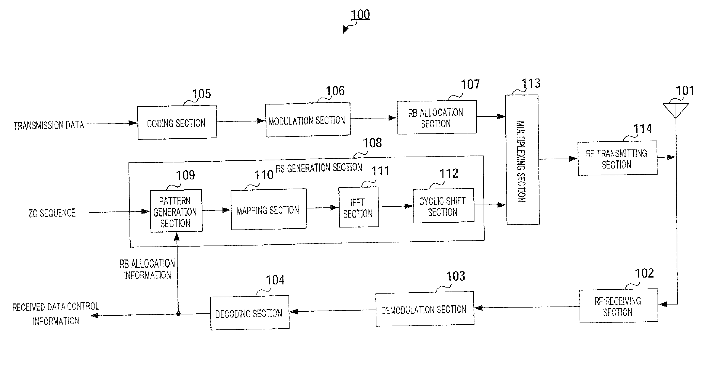
[0051]The configuration of mobile station 100 according to Embodiment 1 will be explained using FIG. 9. RF receiving section 102 performs receiving processing, including down-conversion and A / D conversion, on a signal received via antenna 101, and outputs the signal after the receiving processing to demodulation section 103. Demodulation section 103 performs equalization processing and demodulation processing on the signal after the receiving processing, and outputs the signal after these processing to decoding section 104. Decoding section 104 decodes the signal after the demodulation processing and extracts the data signal and control information. Further, in the extracted control information, the RB (resource block) allocation information is outputted to pattern generation section 109 in RS generation section 108.

[0052]Coding section 105 encodes transmission data and outputs the encoded data to modulation section 106. Modulation section 106 modulates the encoded data and outputs ...

embodiment 2

[0084]Although a case has been explained above with Embodiment 1 where the length of a ZC sequence is a multiple of the number of subcarriers in one RB, a case will be explained with Embodiment 2 of the present invention where the length of a ZC sequence is a prime number.

[0085]Further, the configurations of a mobile station and base station according to Embodiment 2 of the present invention are the same as shown in FIGS. 9 and 10 illustrating Embodiment 1, and therefore will be explained with reference to FIGS. 9 and 10.

[0086]Generally, to adjust a ZC sequence having a sequence length of a prime number to the number of subcarriers in the RS transmission band, studies are underway to generate RSs by cyclic extension and generate RSs by truncation. Now, these RSs will be explained.

[0087]Generally, an RS generated by cyclic extension of a ZC sequence generally uses the ZC sequence having a sequence length of the prime number less than and closet to the number of subcarriers in the RS ...

embodiment 3

[0096]The configuration of mobile station 200 according to Embodiment 3 of the present invention will be explained using FIG. 17. FIG. 17 is different from FIG. 9 in changing RS generation section 108 to RS generation section 201.

[0097]RS generation section 201, which has first cyclic shift section 202, second cyclic shift section 203, DFT section 204, mapping section 205 and IFFT section 206, generates an RS from a ZC sequence and outputs the generated RS to multiplexing section 113. Now, the components of sections in RS generation section 201 will be explained.

[0098]First cyclic shift section 202 cyclically shifts a ZC sequence by a predetermined amount of shift (by the amount of shift assigned per cell or mobile station regardless of the transmission band), the ZC sequence subject to the cyclic shift to second cyclic shift section 203.

[0099]Second cyclic shift section 203 cyclically shifts the ZC sequence further outputted from first cyclic shift section 202 by an amount of shift...


PUM


Abstract

It is possible to provide a radio transmission device and a radio transmission method which can avoid degradation of a channel estimation accuracy using a reference signal formed by a ZC sequence even when the RS transmission band of a local cell is different from that of an adjacent cell. A mobile station decides a cyclic shift sequence corresponding to RB allocation information from an RS table which correlates different frequency bandwidths from a reference point of respective transmission bands to a spectrum start number of the cyclic shift sequence so as to satisfy a particular relationship based on the sequence length and transmits the decided cyclic shift sequence as RS to a base station. The base station uses the same RS table as the RS table of the mobile station and performs correlation calculation of the RS transmitted from the mobile station, thereby performing channel estimation.

Description

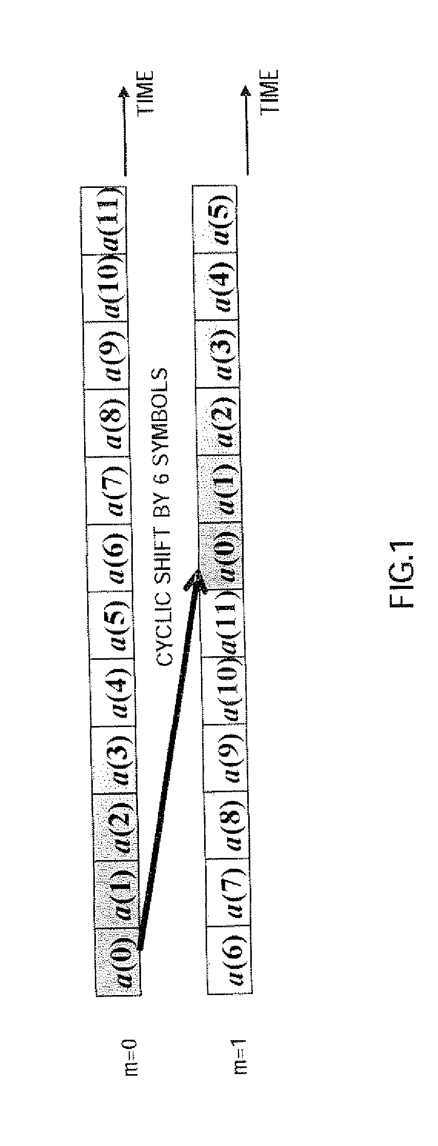
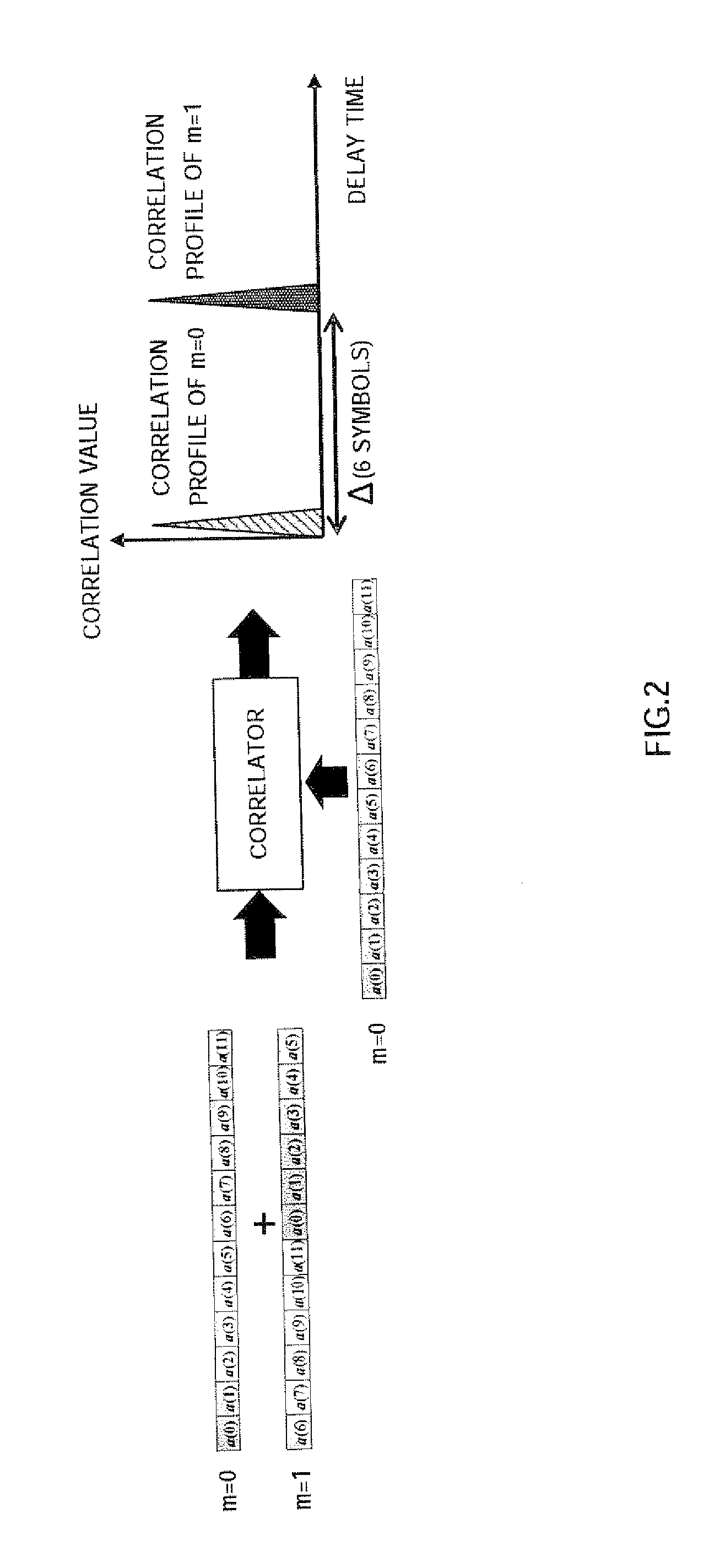
TECHNICAL FIELD[0001]The present invention relates to a radio transmitting apparatus and radio transmission method that use CAZAC sequences (i.e. Constant Amplitude and Zero Auto-correlation Code), including Zadoff-Chu sequences (hereinafter “ZC sequences”), for reference signals (hereinafter “RSs”).BACKGROUND ART[0002]In 3GPP LTE (3rd Generation Partnership Project Long-term Evolution), studies are conduct to use a ZC sequence as an RS in uplink. This ZC sequence is a kind of CAZAC sequence and represented by the following equation 1.(Equation1)ar,m(k)={exp{-j2πrN((k+mΔ)22)},whenNisevenexp{-j2πrN((k+mΔ)(k-mΔ+1)2)},whenNisodd,k=0,1,…,N-1[1]Here, N is the sequence length of the ZC sequence and r is the ZC sequence number (i.e. sequence index), and N and r are coprime. Reasons to study a ZC sequence as an RS include constant frequency response characteristics, good auto-correlation characteristics and good cross-correlation characteristics between sequences (between sequences of diffe...

Claims


Application Information

Patent Timeline
Patent Type & Authority Applications(United States)
IPC IPC(8): H04L27/04H04L27/00H04J13/00H04J13/22
CPCH04J13/0059H04L25/0226H04J13/22
Inventor OGAWA, YOSHIHIKOIMAMURA, DAICHIFUTAGI, SADAKIMATSUMOTO, ATSUSHIIWAI, TAKASHI
Owner PANASONIC INTELLECTUAL PROPERTY CORP OF AMERICA
Learn More