
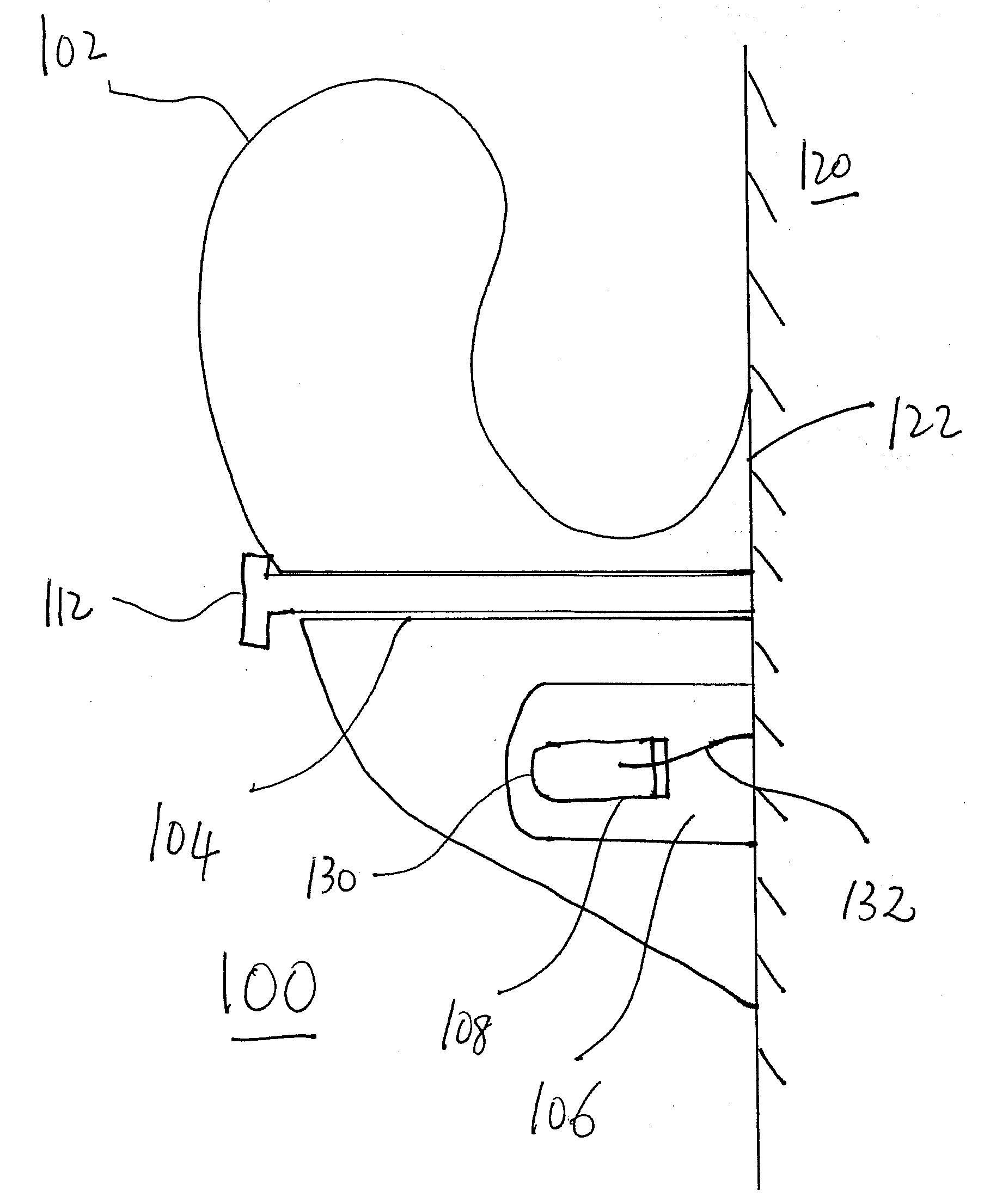
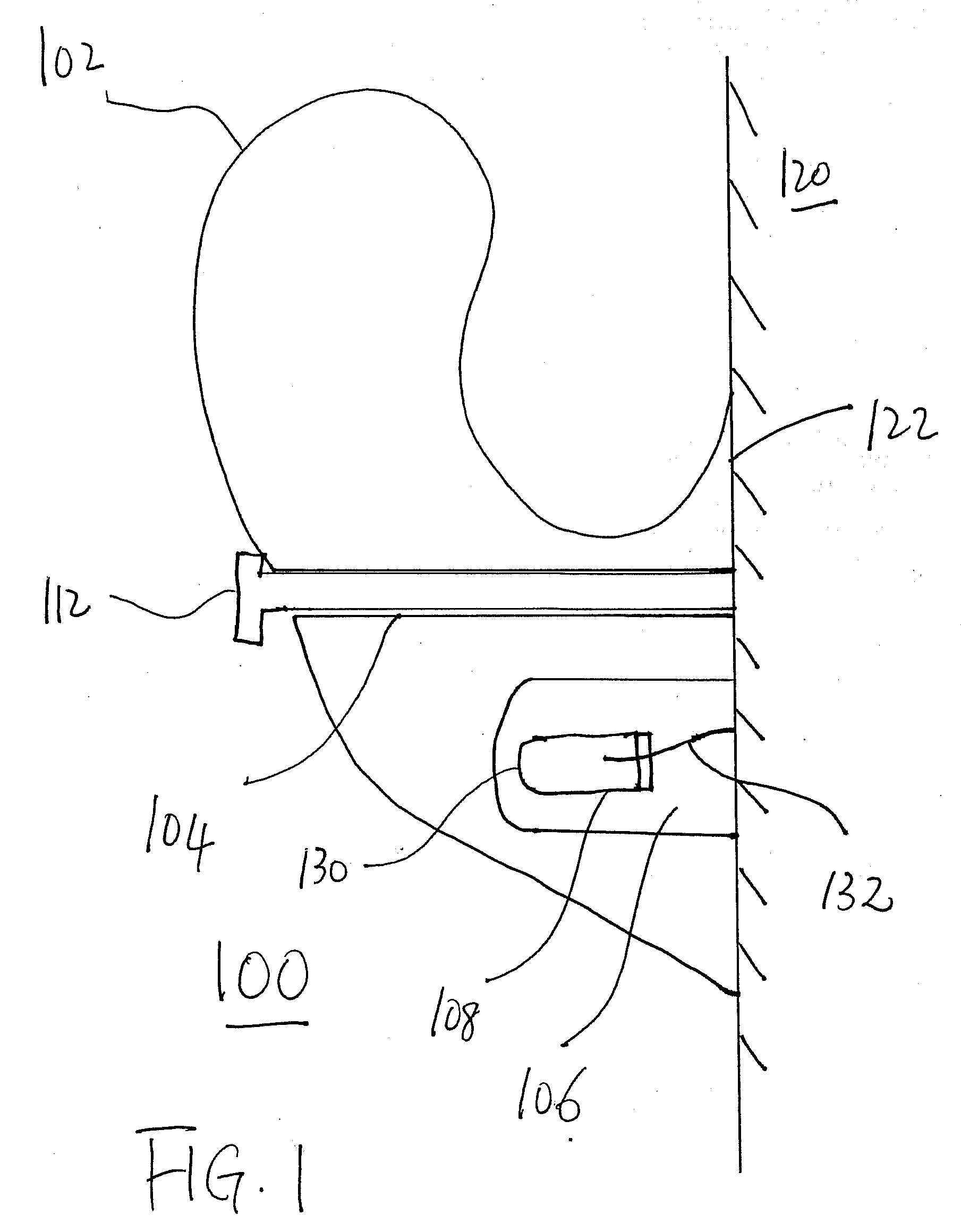
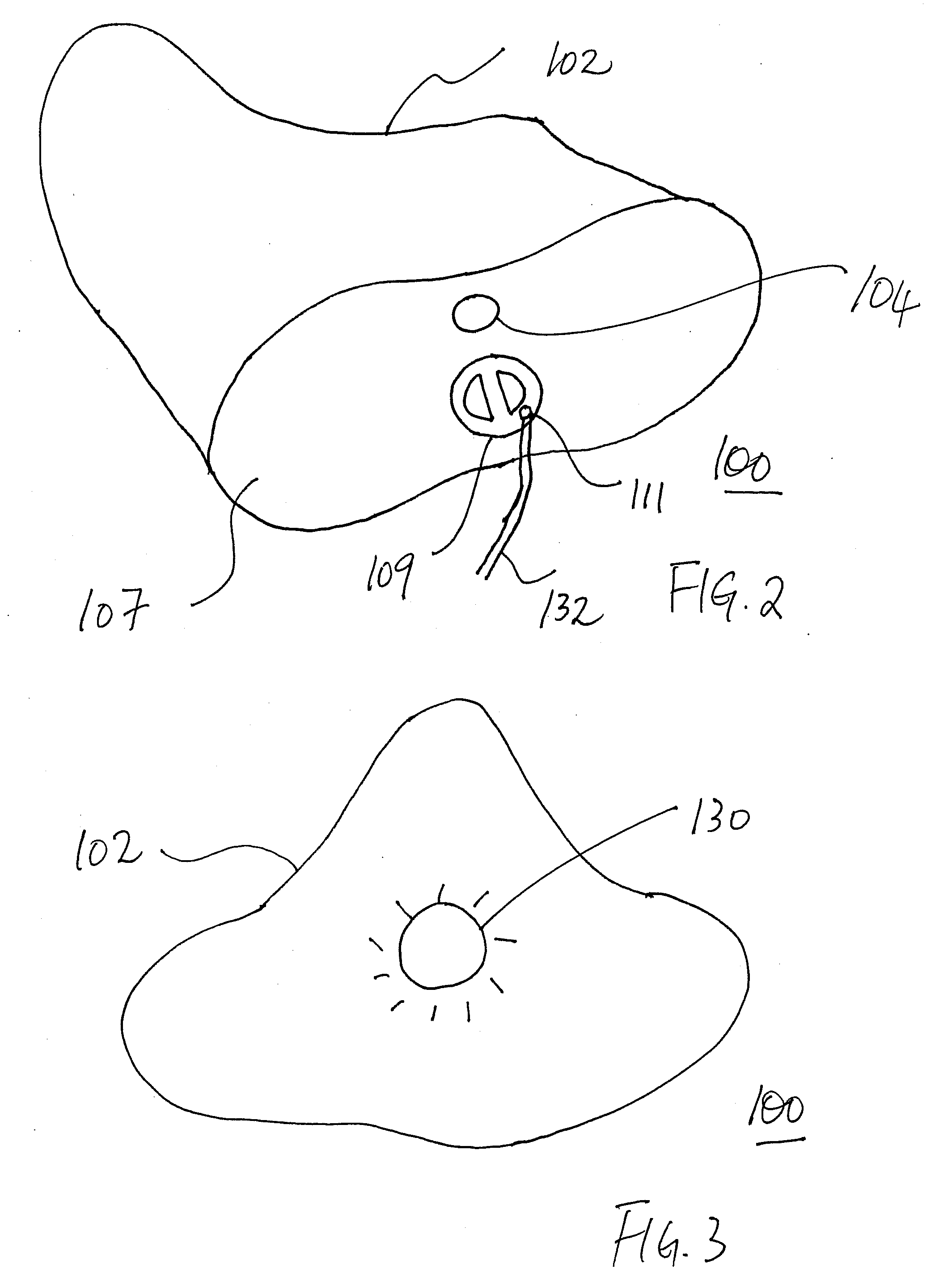
Illuminated rock-climbing hold

a technology of climbing hold and illumination, which is applied in the direction of gymnastic climbing, free-suspended gymnastics, gymnastic exercise, etc., can solve the problems of not easy and convenient to change the pattern of routes, and achieve the effect of enhancing the entertainment value of climbing walls and providing flexibility in changing routes

Inactive Publication Date: 2010-01-07
HENSLEY JOSHUA A
View PDF15 Cites 46 Cited by
  • Summary
  • Abstract
  • Description
  • Claims
  • Application Information

AI Technical Summary

Benefits of technology

[0013]One object and advantage of the present invention is to enhance entertainment values of climbing walls or similar structures. With the present invention, light shows on portable rock walls, cruise ships, climbing centers are viable. In any variation of color of light source and programming, the array of light-up rock climbing holds will provide a new and interesting visual impact for both day and night time climbs.
[0014]Another object and advantage of the present invention is to highlight a preferred climbing route on a climbing wall. Climbers usually choose a route, which is a line of particular climbing holds, before embarking on the actual climb. Climbers sometimes need a spotter to direct them to a certain hold in that route during the climb as it is hard to spot a particular hold once they are on the wall. The present invention, with its self-illumination property, can help climbers to identify their next hold in the route, the past route taken, any preferred or optional routs for future moves, etc.
[0015]Yet another object and advantage of the present invention is to provide flexibility in changing routes on climbing walls. Rather than installing colored climbing holds or marking existing holds with colored tape, the hold can be illuminated manually or remotely, such as by computer or other mechanical or electrical switch.
[0016]Further details, objects and advantages of the present invention will become apparent through the following descriptions, and will be included and incorporated herein.

Problems solved by technology

However, the installation is permanent and it is not easy and convenient to change the pattern of routes.

Method used


Image

  • Illuminated rock-climbing hold
  • Illuminated rock-climbing hold
  • Illuminated rock-climbing hold

Examples


Embodiment Construction

[0023]The description that follows is presented to enable one skilled in the art to make and use the present invention, and is provided in the context of a particular application and its requirements. Various modifications to the disclosed embodiments will be apparent to those skilled in the art, and the general principals discussed below may be applied to other embodiments and applications without departing from the scope and spirit of the invention. Therefore, the invention is not intended to be limited to the embodiments disclosed, but the invention is to be given the largest possible scope which is consistent with the principals and features described herein.

[0024]It will be understood that in the event parts of different embodiments have similar functions or uses, they may have been given similar or identical reference numerals and descriptions. It will be understood that such duplication of reference numerals is intended solely for efficiency and ease of understanding the pres...


PUM


Abstract

An illuminated climbing hold for mounting on a climbing wall, the illuminated climbing hold that consists of a body which has an exterior portion adapted to support a climber and a substantially planar mounting face adapted to engage the climbing wall, the body further consisting of an optional internal compartment and the body is made of transparent building material; an operational light source disposed inside the body, such as inside the compartment, and operational fastening means to attach the climbing hold to a climbing wall.

Description

RELATED APPLICATIONS[0001]This Application is related to U.S. Provisional Patent Application Ser. No. 61 / 134,158 filed Jul. 7, 2008 entitled LIGHT-UP ROCK-CLIMBING HOLD, which is incorporated herein by reference in its entirety, and claims any and all benefits to which it is entitled therefrom.FIELD OF THE INVENTION[0002]This invention relates to an improved climbing hold installed on artificial climbing walls and similar structures, and more particularly to an illuminated climbing hold and a system of mentioned climbing holds which illuminate climbing surface and a climbing route.BACKGROUND OF THE INVENTION[0003]This invention relates to rock-climbing on artificial walls or similar structures, specifically to climbing holds. The concept of the artificial climbing wall began in the United Kingdom. The first wall was created in 1964 at Leeds University by Don Robertson, a lecturer in Physical Education and founder of DR Climbing walls, by inserting pieces of rock into a corridor wall...

Claims


Application Information

Patent Timeline
IPC IPC(8): A63B17/00
CPCA63B69/0048A63B2207/02A63B2225/50A63B2220/801A63B2220/52A63B2225/74
Inventor HENSLEY, JOSHUA A.
Owner HENSLEY JOSHUA A
Learn More