Gas-driven chest compression apparatus

a compression apparatus and gas-driven technology, applied in the field of gas-driven chest compression apparatus, can solve the problems of complex control, complex valve system, and large volume of known apparatus, and achieve the effect of reducing the amount of pressure, and reducing the volume of known apparatus

Inactive Publication Date: 2010-01-07
PHYSIO CONTROL INC
View PDF4 Cites 45 Cited by
  • Summary
  • Abstract
  • Description
  • Claims
  • Application Information

AI Technical Summary

Benefits of technology

[0015]According to a sixth preferred aspect of the invention an actuator is provided with a resiliently compressible means such as a steel coil that accelerates the return from an inflated state to a non-inflated state. It is preferred for the resiliently compressible means to partially or fully enclose the actuator.

Problems solved by technology

The consumption of pressurized gas can be substantial and is a limiting feature on the use of the apparatus in places where supply of pressurized driving gas is limited.
The consecutive supply of driving gas to the two chambers of the known apparatus requires a complex and thus expensive valve system and a correspondingly complex control.

Method used


Image

  • Gas-driven chest compression apparatus
  • Gas-driven chest compression apparatus
  • Gas-driven chest compression apparatus

Examples


third embodiment

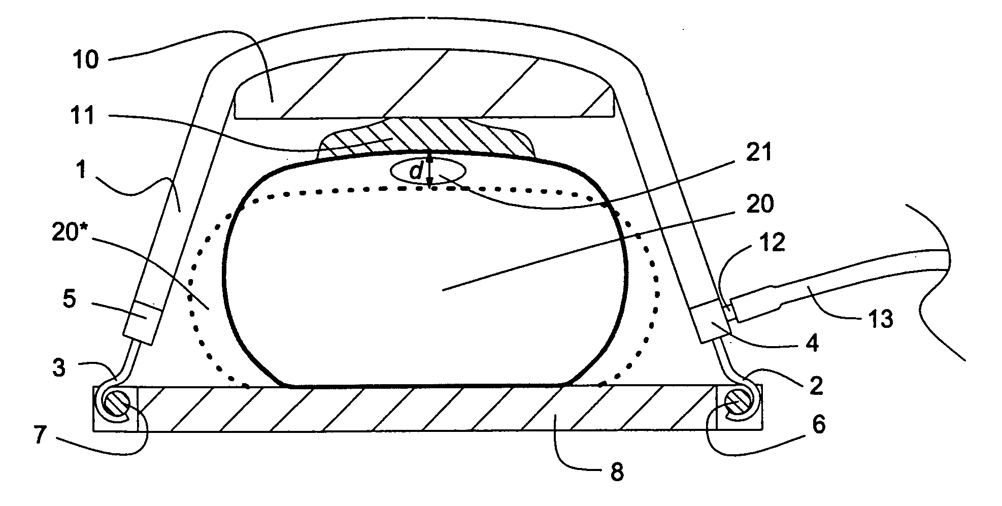
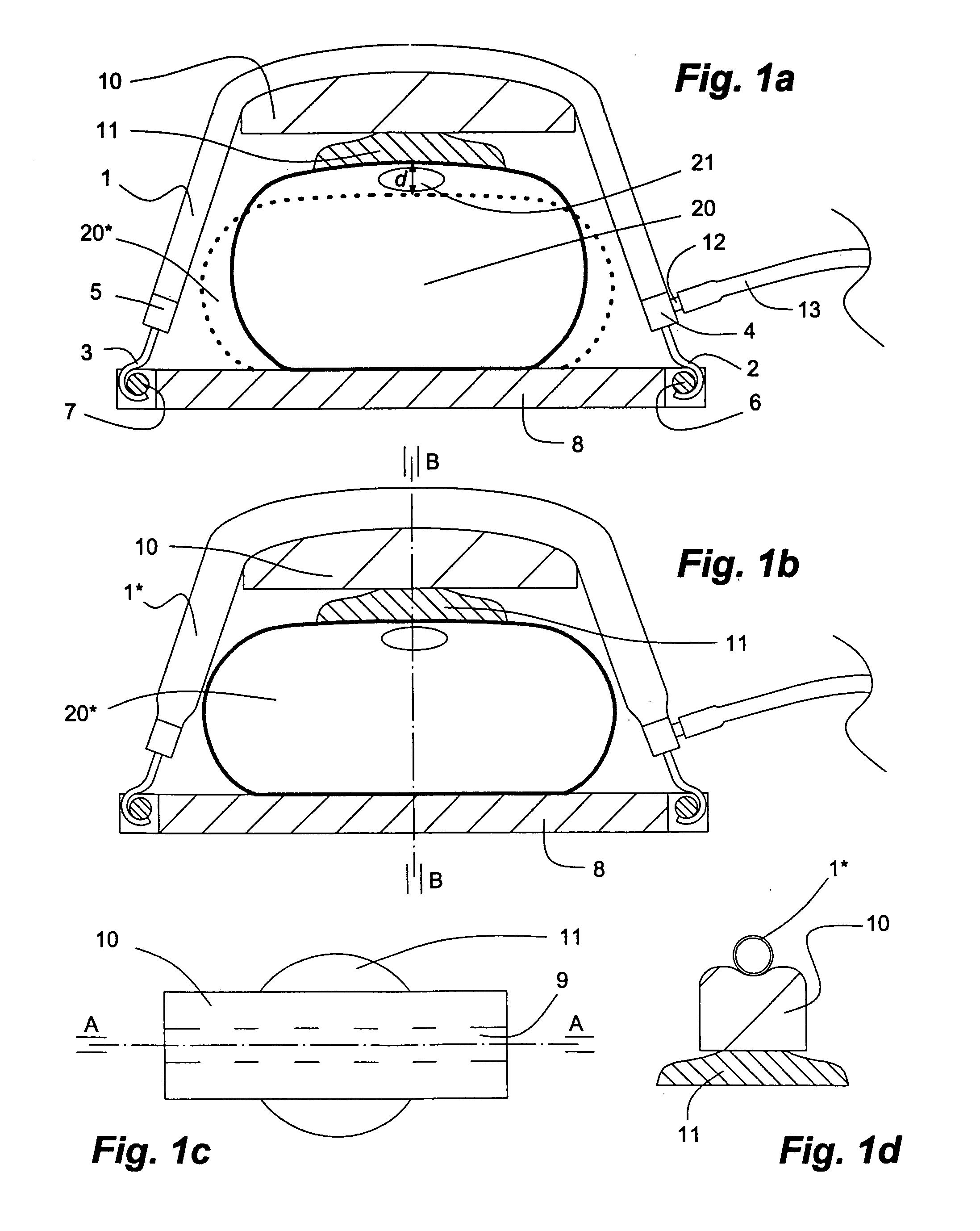
[0044]the apparatus of the invention shown in FIGS. 3a and 3b comprises two pneumatic actuators 201, 231 of equal length and properties (inner diameter: 20 mm; length: 40 cm). The actuators 201, 231 have hooks 203, 202 extending axially from their first ends 205, 204, by which they are attached to eyes 207, 206 fixed to and extending from opposite short sides of a rectangular back plate 208. From the second ends of the actuators 201, 231 rods carrying terminal eyes 226, 225 extend in axial directions. The eyes 226, 225 are mounted on bars 228, 227 bridging slits 230, 229 in a base plate 210. The rod 239 of a compression pad 211 is mounted displaceably in a central through bore of the base plate 210, of which a portion extending from the upper end is threaded. Compressed air is fed to the actuators 201, 231 by branches 213, 223 of a flexible high pressure gas hose. The apparatus is mounted to the patient's chest 220 in the following manner: the compression pad 211 with the rod 239 di...

fifth embodiment

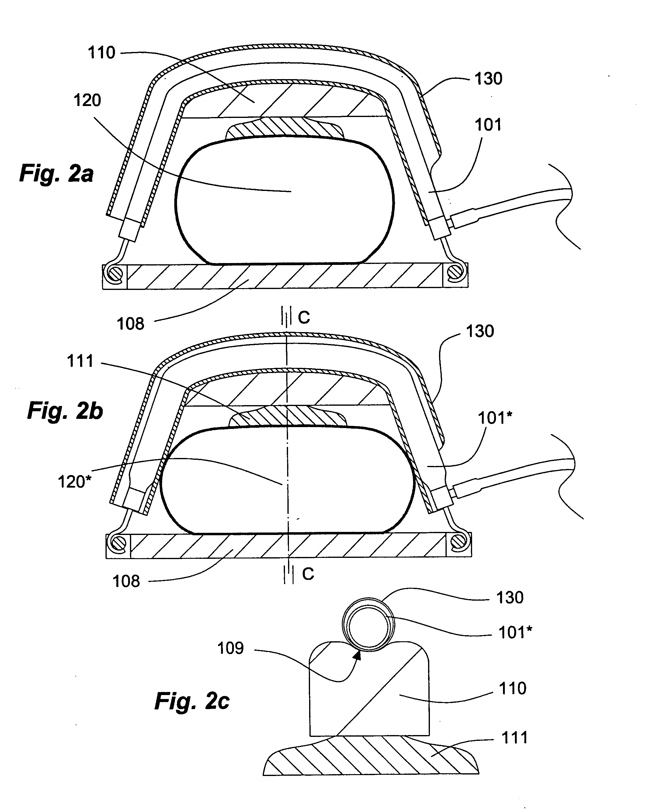
[0046]In the apparatus of the invention similar to that of FIGS. 3a, 3b in respect of the use of two actuators of same size and properties, the actuators, of which only one actuator 401* is shown in FIG. 5 in an inflated state, are working against a resiliently compressible means. One reason for this arrangement is to make the first inflated actuator 401* and the second inflated actuator (not shown) return to their original non-inflated configuration as soon as they are deflated. In the embodiment of FIG. 5, the resiliently compressible means is a steel coil 440 held between first and second support flanges 441, 442 of the actuator's 401 first and second end pieces, respectively. A hook 405, by which the apparatus is fastened at an eye 407 of the back plate 408, is mounted in a central bore of the first end piece. The female part 426 of a ball-and-socket joint is mounted at the actuator's 401* second end piece, while the male part 428 is mounted in a threaded bore a base plate 410. ...

sixth embodiment

[0049]the apparatus of the invention illustrated in FIG. 7 with its actuator 601* in a an expanded (active) state comprises a compression plate 611* disposed between the chest 620* of a patient and the actuator 601* in a bended state. The resiliently flexible oblong compression plate 611, which is shown in a top view and a side view in FIGS. 7a and 7b, respectively, in an unloaded (not bended) state, is substantially flat except for a longitudinally extending slot 612. In a mounted state the actuator 601 is disposed in the slot 612 to keep the compression plate 611 from moving in a cranial or opposite direction in respect of the actuator 611. The resilient nature of the compression plate 611, which seeks to regain its original flat state from the bended state shown in FIG. 7, supports the actuator in assuming its full length or inactive state 611 at the end of the compression phase. Elements identified in FIG. 7 by reference numbers 604, 608, 615 correspond to elements 504, 508, 515...


PUM


Abstract

A gas-driven chest compression apparatus for cardiopulmonary resuscitation (CPR) comprises a flexible pneumatic actuator, capable of axial contraction when fed with a pressurized driving gas, and means for controlling the contraction thereof. Also disclosed are methods of providing chest compressions to a patient by means of a CPR apparatus comprising actuator(s) of this kind, and a corresponding use of the actuator.

Description

FIELD OF THE INVENTION[0001]The present invention relates to a gas-driven chest compression apparatus for cardiopulmonary resuscitation.BACKGROUND OF THE INVENTION[0002]Sudden cardiac arrest is commonly treated mechanically and / or by electrical defibrillation. Mechanical treatment may be given manually or by a chest compression apparatus. A number of chest compression apparatus are known in the art, such as the pneumatically driven LUCAS™ mechanical chest compression system (“Lucas™ system”; an apparatus for compression and physiological in Cardio-Pulmonary Resuscitation, CPR, manufactured by Jolife AB, Lund, Sweden). Specifically the Lucas™ system comprises a support structure and a compression unit. The support structure includes a back plate for positioning under the patient's back posterior to the patient's heart and a front part for positioning around the patient's chest anterior to the heart. The front part has two legs, each having a first end pivotally connected to a hinge o...

Claims


Application Information

Patent Timeline
Patent Type & Authority Applications(United States)
IPC IPC(8): A61H31/00
CPCA61H31/006A61H31/008A61H2201/5071A61H2201/1238A61H2201/0173
Inventor KING, BEN
Owner PHYSIO CONTROL INC
Why Eureka
Try Eureka