Vehicle drive system

a technology of drive system and drive shaft, which is applied in the direction of machines/engines, positive displacement liquid engines, transportation and packaging, etc., can solve the problems of low oil pump efficiency, large flow of oil, and circuit damage, so as to improve efficiently return to the oil pump. , the effect of improving the efficiency of the oil pump

Active Publication Date: 2011-09-29
AISIN AW CO LTD +1
View PDF6 Cites 16 Cited by
  • Summary
  • Abstract
  • Description
  • Claims
  • Application Information

AI Technical Summary

Benefits of technology

Thus, the return oil passage can be made short so that oil discharged from the pressure regulating valve can be efficiently returned to the oil pump. Therefore, the efficiency of the oil pump can be improved because of the improved return of oil.
According to a vehicle drive system of the present invention, as described above, a motor generator can be efficiently cooled while suppressing an in-circuit hydraulic pressure increase.

Problems solved by technology

However, while the motor cooling circuit necessitates a large flow of oil, a large flow of oil is not desirable for the lubricating circuit.
Greater oil passing resistance in the lubricating circuit may result in circuit damage due to the increased hydraulic pressure inside the circuit (especially near the oil cooler), lower oil pump efficiency, and other problems.

Method used


Image

  • Vehicle drive system
  • Vehicle drive system
  • Vehicle drive system

Examples


Embodiment Construction

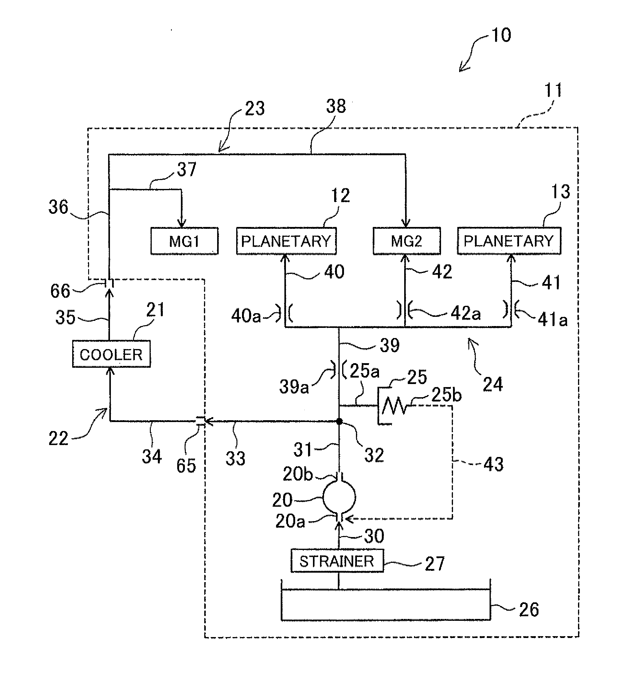
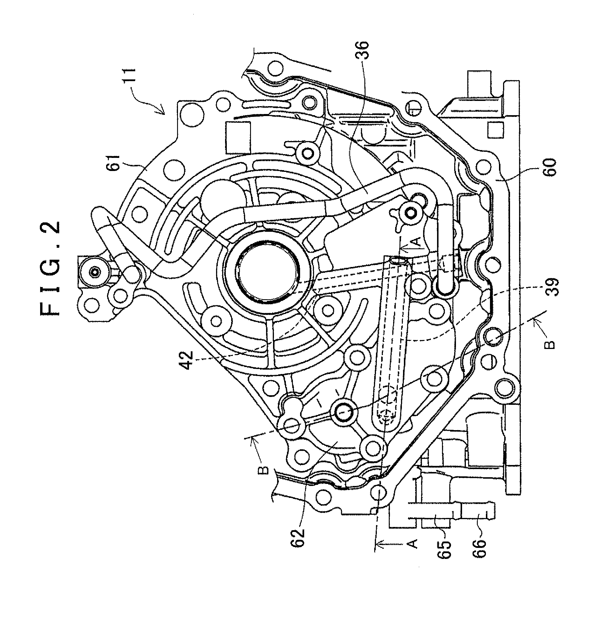
Hereinafter, a specific preferred embodiment of a vehicle drive system according to the present invention will be described in detail based on the drawings. The present embodiment is an example that applies the present invention to a drive system installed in a hybrid vehicle. The vehicle drive system according to the present embodiment will be described with reference to FIGS. 1 to 4. FIG. 1 is a drawing that shows the constitution of a hydraulic circuit of the drive system according to the embodiment. FIG. 2 is a drawing that shows the schematic constitution near a cover of a motor generator MG2 of the vehicle drive system as viewed from a front planetary gear unit side. FIG. 3 is a cross-sectional view taken along a line A-A in FIG. 2. FIG. 4 is a cross-sectional view taken along a line B-B in FIG. 2.

As shown in FIG. 1, a drive system 11 according to the present embodiment includes a hydraulic control device 10, a motor generator MG1, a front planetary gear unit 12, a motor gener...


PUM


Abstract

A vehicle drive system, including a motor generator; a gear group having a plurality of gears; and a motor cooling circuit for cooling the motor generator. The system further includes a lubricating circuit for lubricating the gear group; a cooler circuit in which an oil cooler is provided; and an oil pump that supplies oil to each circuit. The motor cooling circuit is arranged in series with and downstream of the cooler circuit, and the lubricating circuit is arranged parallel to the cooler circuit with respect to the oil pump.

Description

INCORPORATION BY REFERENCEThe disclosure of Japanese Patent Application No. 2010-074876 filed on Mar. 29, 2010 including the specification, drawings and abstract is incorporated herein by reference in its entirety.BACKGROUND OF THE INVENTIONThe present invention relates to a vehicle drive system that includes a motor generator.DESCRIPTION OF THE RELATED ARTIn a vehicle drive system that includes a motor generator and is installed in a hybrid, electric, or other vehicle, the motor generator is incorporated inside a case. The motor generator generates heat while driving and must be cooled. This is because the generated heat lowers the performance of the motor generator.Therefore, the vehicle drive system that includes the motor generator may also include a motor cooling circuit for supplying oil to cool the motor generator. In such a vehicle drive system, the motor generator is cooled by supplying oil discharged from an oil pump to the motor generator (mainly a stator core and a coil ...

Claims


Application Information

Patent Timeline
Patent Type & Authority Applications(United States)
IPC IPC(8): F04B49/00B60K11/04F16H57/04H02K9/02
CPCB60K6/445Y02T10/6239F16H57/0476F16H57/0413Y10T137/85986Y02T10/62
Inventor MATSUSHITA, JUNJIISOGAI, AKIRAIIMURA, DAISUKETOYODA, HIRONARI
Owner AISIN AW CO LTD
Why Eureka
Try Eureka