Display device and illumination device

a technology of illumination device and display device, which is applied in the direction of identification means, instruments, optical light guides, etc., can solve the problems of many light loss in bonding method, and achieve the effect of reducing light loss

Active Publication Date: 2017-08-10
SATURN LICENSING LLC
View PDF5 Cites 17 Cited by
  • Summary
  • Abstract
  • Description
  • Claims
  • Application Information

AI Technical Summary

Benefits of technology

[0004]However, many light losses may occur in a bonding method in Patent Literature 1. It is desirable to achieve a light guide plate unit that makes it possible to reduce light losses.

Problems solved by technology

However, many light losses may occur in a bonding method in Patent Literature 1.

Method used


Image

  • Display device and illumination device
  • Display device and illumination device
  • Display device and illumination device

Examples


embodiment

[Configuration]

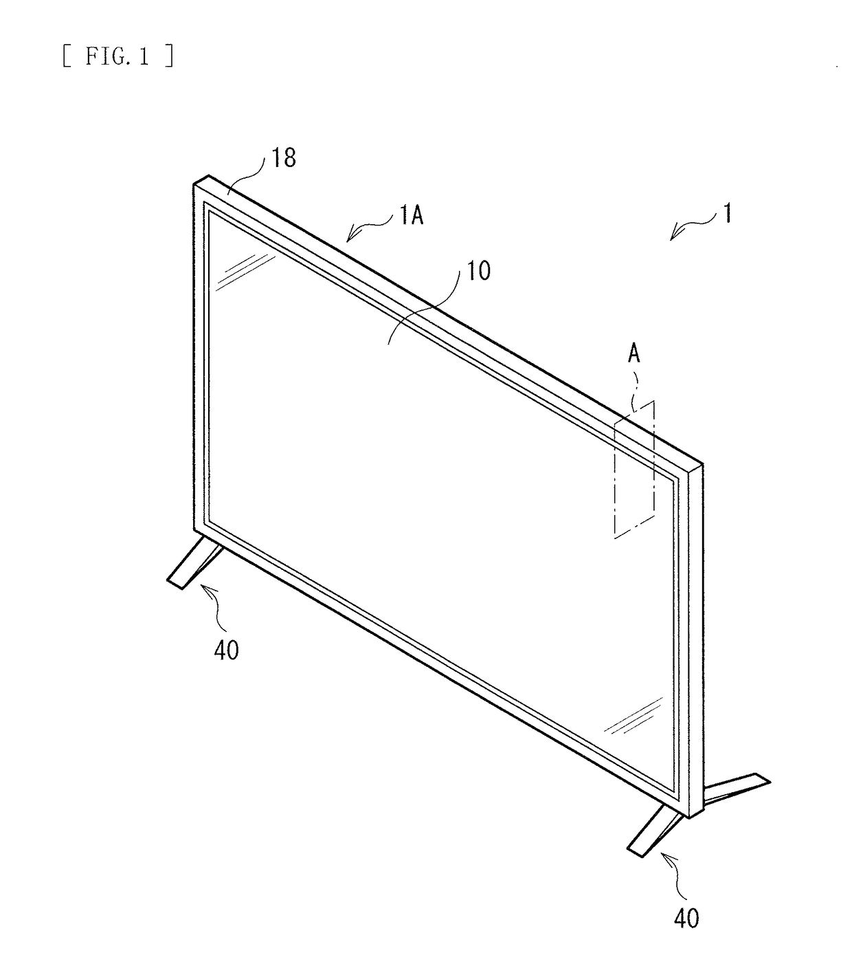
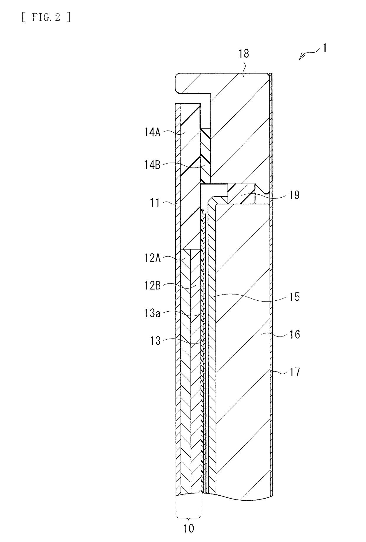
[0028]FIG. 1 illustrates an outer appearance of a display device (a display device 1) according to an embodiment of the present disclosure. FIG. 2 illustrates a cross-sectional configuration example of a portion A in FIG. 1. The display device 1 may be a display device used as a television, for example. The display device 1 may include, for example, a main body 1A including a display panel (a liquid crystal panel 10) and an illumination section (such as a light guide plate unit 16, for example), and a stand 40. The illumination section may illuminate the liquid crystal panel 10. In the main body 1A, the liquid crystal panel 10 and the light guide plate unit 16 may be supported by, for example, a frame 18, and form a flat plate shape as a whole. Various kinds of optical sheets are bonded to each of the liquid crystal panel 10 and the light guide plate unit 16.

[0029]More specifically, a sealing resin layer 14A may be formed to cover an outer edge of the liquid crystal p...

modification example

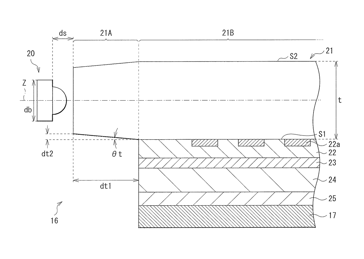
[0065]FIG. 12 illustrates a configuration of a main portion of a light guide plate unit according to a modification example. In the foregoing embodiment, the low refractive index layer 23 is interposed between the adhesive layer 22 and the reflection sheet 24; however, the low refractive index layer 23 may not be provided. In other words, as with the present modification example, the adhesive layer 22 may be provided adjacent to the surface S1 of a light guide plate 30, and the reflection sheet 24 may be provided adjacent to the adhesive layer 22. In this case, as the reflection sheet 24, for example, a metal film such as silver or aluminum or a multilayer light interference reflection film may be used. Moreover, in the foregoing embodiment, the light entry section 21A having a tapered shape is provided to face the light source 20; however, the light entry section 21A may not be necessarily provided. The light shielding sheet 17 may be bonded on the back surface side of the reflecti...


PUM


Abstract

A display device includes a display panel and an illumination section that illuminates the display panel. The illumination section includes: a light guide plate having a first surface and a second surface facing each other; a light source facing an end surface of the light guide plate; an adhesive layer formed adjacent to the first surface of the light guide plate and having substantially the same refractive index as a refractive index of the light guide plate; and a light reflection layer bonded to the first surface of the light guide plate with at least the adhesive layer in between.

Description

TECHNICAL FIELD[0001]The present disclosure relates to a display device and an illumination device that are used for a television or any other apparatus.BACKGROUND ART[0002]In a display device such as a liquid crystal display device, a backlight is provided on a back surface of a display panel. An example of the backlight may be a surface-emitting illumination device using, for example, a light guide plate. In such an illumination device, a reflection plate is provided on back surface side of the light guide plate, and there is proposed a configuration in which the reflection plate is bonded to a back surface of the light guide plate (refer to Patent Literature 1, for example).CITATION LISTPatent Literature[0003][Patent Literature 1] Japanese Unexamined Patent Application Publication No. 2013-093195SUMMARY OF INVENTION[0004]However, many light losses may occur in a bonding method in Patent Literature 1. It is desirable to achieve a light guide plate unit that makes it possible to re...

Claims


Application Information

Patent Timeline
Patent Type & Authority Applications(United States)
IPC IPC(8): F21V8/00
CPCG02B6/0043G02B6/002G02B6/0085G02B6/0055G02B6/0088G02B6/0093G02B6/0065G02B6/0046G02B6/005G02B6/0051G09F9/35
Inventor ARAKI, SOYASUMIDA, TAKAOYAMAMOTO, TAKESHIYOSHIMATSU, TOMOYUKI
Owner SATURN LICENSING LLC
Why Eureka
Try Eureka