Windshield wiper

a wiper and windshield technology, applied in the field of windshield wipers, can solve the problems of easy deformation and deterioration, frequent replacement, and delicate rubber blades, and achieve the effect of improving life span and not easily deformation or deterioration

Inactive Publication Date: 2010-01-14
UNIPOINT ELECTRIC MANUFACTURING CO LTD
View PDF4 Cites 42 Cited by
  • Summary
  • Abstract
  • Description
  • Claims
  • Application Information

AI Technical Summary

Benefits of technology

[0014]The beam that is held firmly on the rubber blade, and the clips hold the beam stably on the rubber blade. Therefore, the rubber blade is connected firmly to other components of the windshield wiper, will not deform or deteriorate easily and has improved life span.

Problems solved by technology

The rubber blade (91) is delicate, deforms and deteriorates easily and has to be replaced frequently.

Method used


Image

  • Windshield wiper
  • Windshield wiper
  • Windshield wiper

Examples


Embodiment Construction

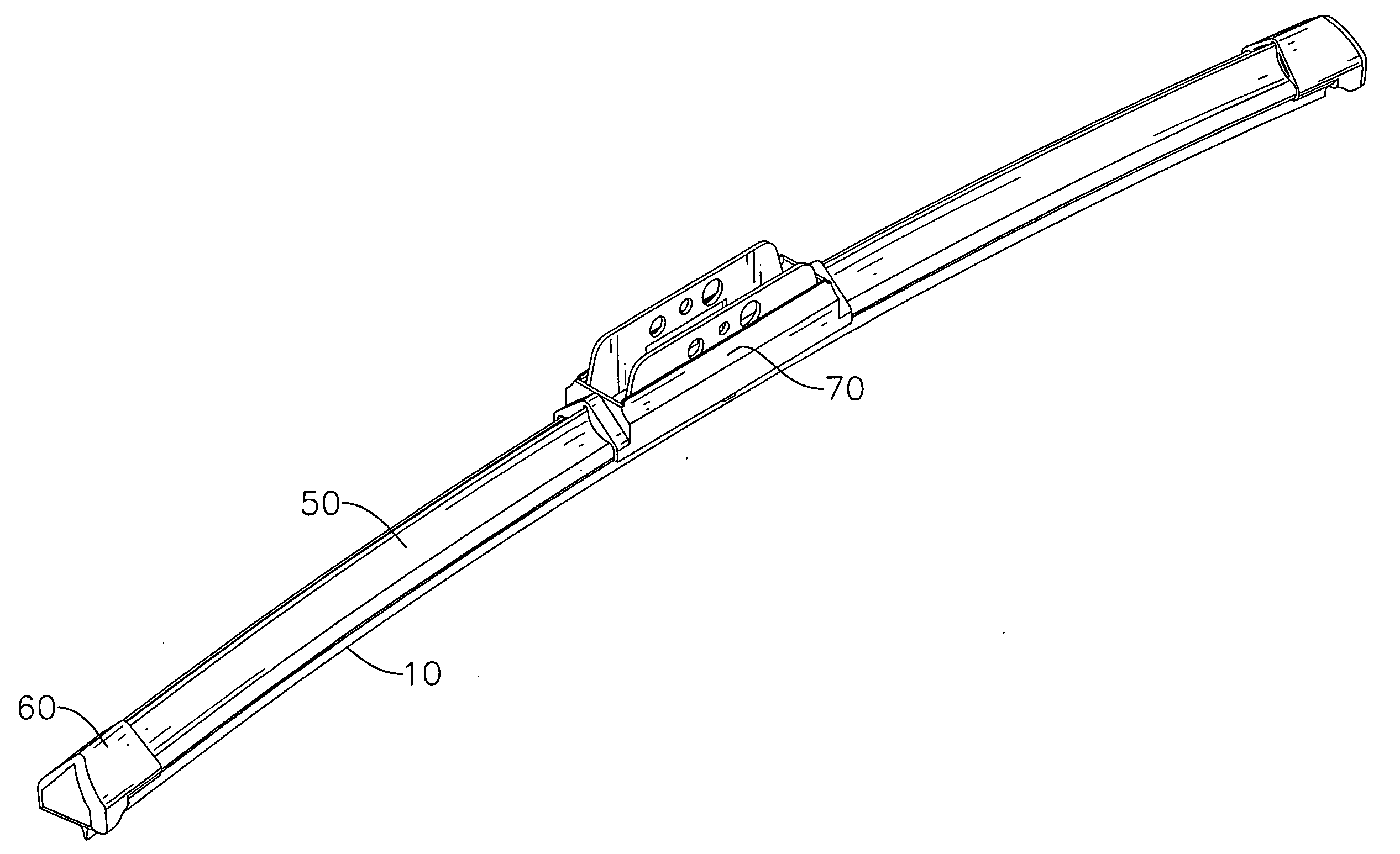
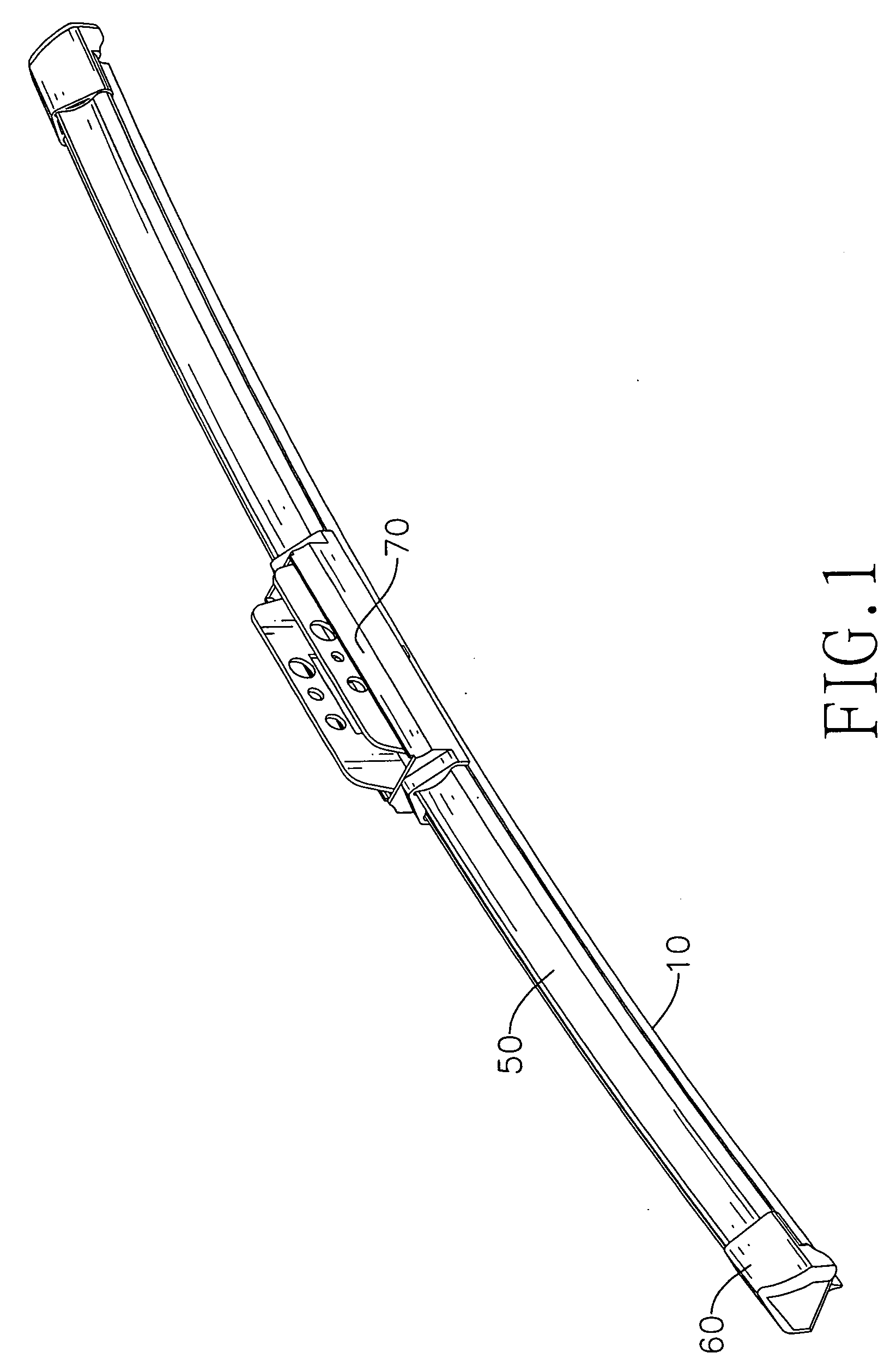
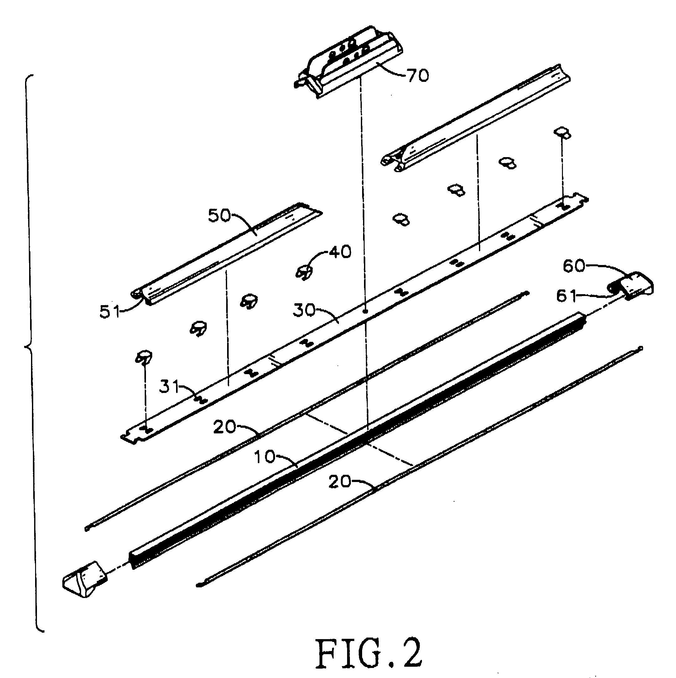
[0026]With reference to FIGS. 1, 2 and 7, a windscreen wiper in accordance with the present invention comprises a rubber blade (10), at least one pair of pads (20), an beam (30), multiple clips (40A, 40B), multiple spoilers (50), two end caps (60) and a connector assembly (70).

[0027]With reference to FIGS. 2 and 3, the rubber blade (10) has a back surface, two opposite sidewalls, two ends and two clip recesses (11) and may have at least one pair of pad recesses (12). The back surface of the rubber blade (10) has two opposite longitudinal edges. The clip recesses (11) are longitudinal, are formed respectively and oppositely in the sidewalls of the rubber blade (10). Each pair of the at least one pair of pad recesses (12) are longitudinal, are formed respectively and oppositely in the sidewalls of the rubber blade (10) between the clip recesses (11) and the back surface of the rubber blade (10).

[0028]Each pair of the at least one pair of pads (20) are longitudinal, are mounted respect...


PUM


Abstract

A windscreen wiper has a rubber blade, an beam being mounted on the rubber blade, multiple clips being mounted respectively through the beam, multiple spoilers being mounted on the beam, two end caps being mounted respectively on the spoiler and around the ends of the beam and the rubber blade and a connector assembly being mounted securely on the beam and between two adjacent spoilers. The beam that is held firmly on the rubber blade, and the clips hold the beam stably on the rubber blade. Therefore, the rubber blade is connected firmly to other components of the windscreen wiper, will not deform or deteriorate easily and has improved life span.

Description

BACKGROUND OF THE INVENTION[0001]1. Field of the Invention[0002]The present invention relates to a windshield wiper, especially to a windshield wiper that has a strengthened structure and will not deform or deteriorate easily so has improved life span.[0003]2. Description of the Prior Arts[0004]A windshield wiper is mounted on a windshield of a car and is pivoted back and forth over the windshield to wipe rain and dirt from the windshield to keep the windshield clean.[0005]With reference to FIGS. 9 and 10, a conventional windshield wiper (90) comprises a rubber blade (91), two pads (92), four inner frames (93), two middle frames (94) and an outer frame (95).[0006]The rubber blade (91) and has a back surface, two opposite sidewalls, two clip recesses (911) and two pad recesses (912). The clip recesses (911) are formed respectively and oppositely in the sidewalls of the rubber blade (91). The pad recesses (912) are formed respectively and oppositely in the sidewalls of the rubber blad...

Claims


Application Information

Patent Timeline
Patent Type & Authority Applications(United States)
IPC IPC(8): B60S1/40
CPCB60S1/381B60S1/3881B60S1/3879B60S1/3858
Inventor CHIEN, CHING-CHUAN
Owner UNIPOINT ELECTRIC MANUFACTURING CO LTD
Why Eureka
Try Eureka