
Image correction apparatus and method

Inactive Publication Date: 2010-01-14
CANON KK
View PDF11 Cites 2 Cited by
  • Summary
  • Abstract
  • Description
  • Claims
  • Application Information

AI Technical Summary

Benefits of technology

[0007]The present invention is directed to an image correction apparatus capable of obtaining a good image through simple processing.

Problems solved by technology

In the conventional art described above, if fractions of pixels appear in edges of an image during the reduction processing, there is a problem that the deviation of pixel position may become large in enlargement processing when the pixel data of fraction portions is discarded.

Method used


Image

  • Image correction apparatus and method
  • Image correction apparatus and method
  • Image correction apparatus and method

Examples


Embodiment Construction

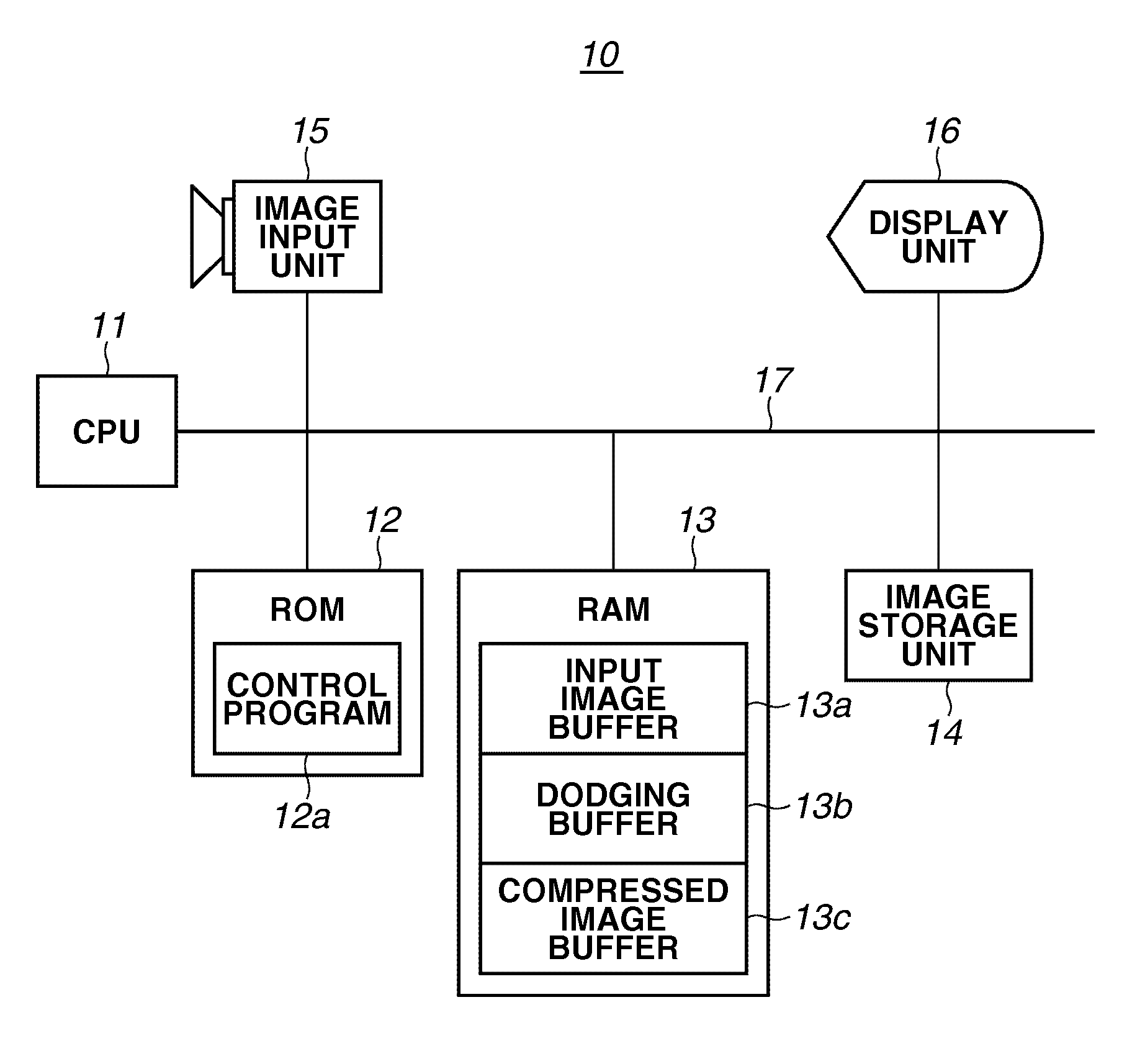
[0021]Various exemplary embodiments, features, and aspects of the invention will be described in detail below with reference to the drawings.

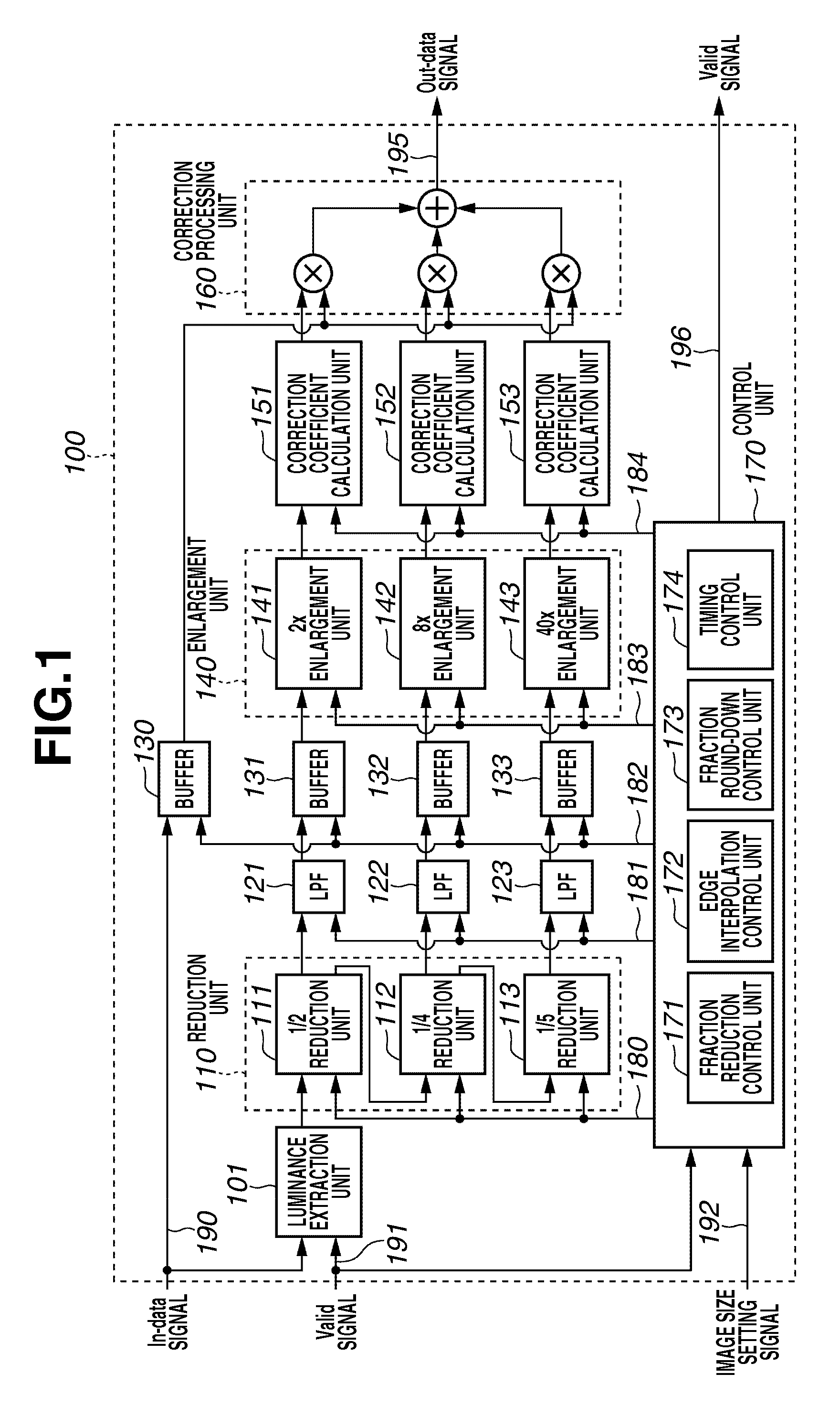
[0022]FIG. 1 illustrates an example of a configuration of an image processing apparatus according to an exemplary embodiment of the present invention. FIG. 1 mainly illustrates a configuration of the image processing apparatus for performing a digital dodging process. As illustrated in FIG. 1, the image processing apparatus 100 includes a luminance extraction unit 101, a reduction unit 110, low-pass filters (LPFs) 121 to 123, buffers 130 to 133, an enlargement unit 140, correction coefficient calculation units 151 to 153, a correction processing unit 160, and a control unit 170.

[0023]Input signals to the image processing apparatus 100 include an input image data signal (In-data signal) 190, a valid input data signal (Valid signal) 191, and an image size setting signal 192. The input image data signal 190 is color image data made up of three typ...


PUM


Abstract

An image correction apparatus reduces an input image, for each area, at a reduction ratio corresponding to the area, generates a reduced luminance image, and extracts a low-frequency component image from the reduced luminance image. The image correction apparatus enlarges the extracted low-frequency component image, for each area, at an enlargement ratio corresponding to the area, generates correction data according to a size of the input image, and corrects the input image according to the correction data.

Description

BACKGROUND OF THE INVENTION[0001]1. Field of the Invention[0002]The present invention relates to an image correction apparatus and method that corrects an input image.[0003]2. Description of the Related Art[0004]In recent years, a camera having a wide dynamic range, i.e., a so-called wide dynamic range camera, capable of clearly photographing both a very bright object and a dark object existing at the same time in the same angle of view is attracting attention.[0005]To enable photographing with such a wide dynamic range, a dodging process can be performed in a dark room for silver-halide photography. There is available a technique (hereinafter, referred to as “digital dodging”) which achieves the dodging process by digital image processing to correct an object having a brightness difference, particularly, a backlit object. A conventional art relating to the digital dodging process is discussed in, for example, U.S. Patent Application Publication No. US 2006 / 0045377. In U.S. Patent A...

Claims


Application Information

Patent Timeline
IPC IPC(8): H04N5/217G06T3/40H04N1/393
CPCH04N5/2628H04N5/2355H04N23/741
Inventor IWABUCHI, KIYOSHI
Owner CANON KK
Learn More