Supercharge Your Innovation With Domain-Expert AI Agents!

Flat Display Apparatus

a technology for display apparatuses and flat panels, which is applied in the direction of electric apparatus casings/cabinets/drawers, furniture parts, instruments, etc., can solve the problems of inability to take into account thermal radiation in the state of wall-mounted installation, inhibit the thickness of the display apparatus, and not be taken into account. achieve optimal installation state, stable installation of the flat display apparatus, and not inhibit efficiency

Active Publication Date: 2010-01-14
MAXELL HLDG LTD
View PDF3 Cites 6 Cited by
  • Summary
  • Abstract
  • Description
  • Claims
  • Application Information

AI Technical Summary

Benefits of technology

The present invention provides a flat display apparatus with an optimal installation state in the wall close installation. The technical problem addressed is the need for an improved thermal radiation efficiency in the display apparatus, while also considering the impact of the installation position on the effectiveness of thermal radiation and the feasibility of cooling the display apparatus. The solution involves a cooling device that includes a first far infrared ray transfer member and a second far infrared ray transfer member, which are thermally connected to the heating element and the outside of the housing, respectively. The radiating surface of the first far infrared ray transfer member and the absorbing surface of the second far infrared ray transfer member are disposed to oppose each other with the housing interposed therebetween, allowing for efficient heat radiation. The support member includes a first support member and a second support member that slidably reciprocates with respect to the first support member, providing flexibility in installation position.

Problems solved by technology

However, in the technique described in JP-A-2002-162910, since the air-flow space is provided for dedicated use, it inhibits the display apparatus from being thinner.
In addition, changing the installation position between the wall closely installation and the desk installation at any time, or the like has not been taken into consideration.
However, in the technique described in JP-A-2007-322752, there is no consideration for the thermal radiation in a state of the wall-mounted installation.

Method used


Image

  • Flat Display Apparatus
  • Flat Display Apparatus
  • Flat Display Apparatus

Examples


Embodiment Construction

[0025]Hereinafter, an embodiment of the present invention will be described with reference to the accompanying drawings.

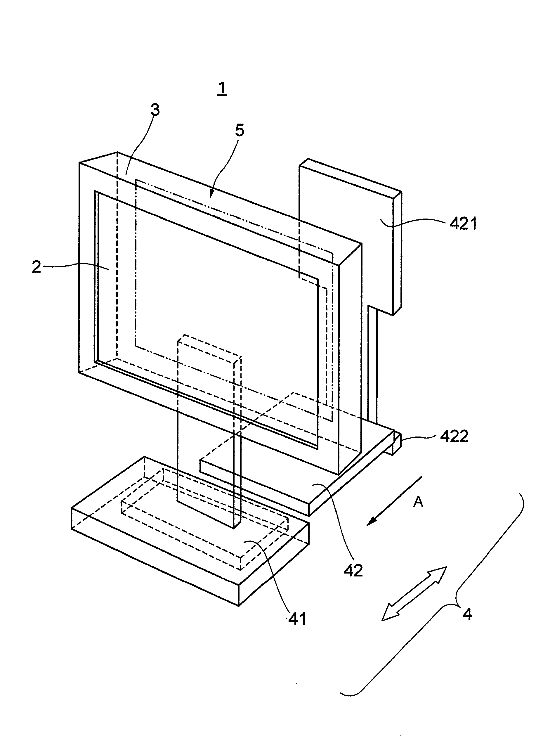
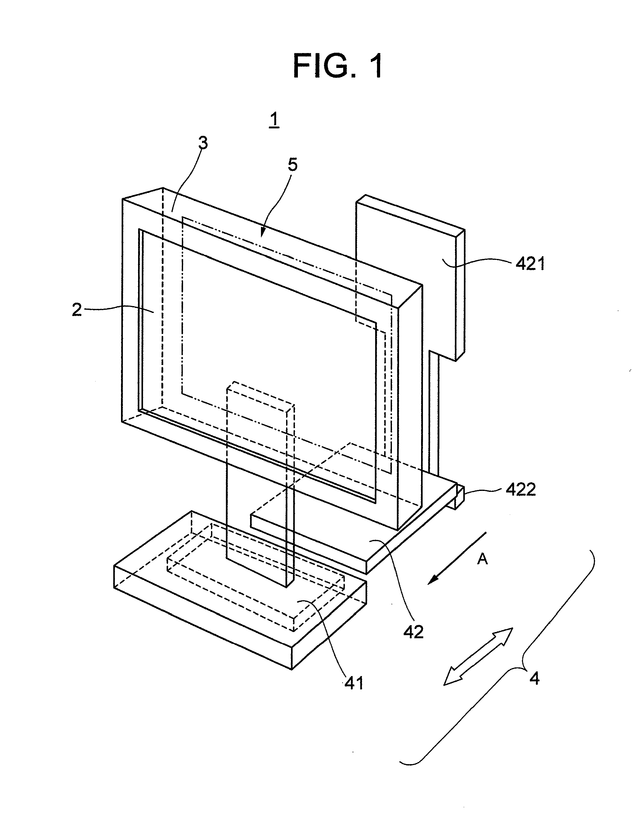
[0026]FIG. 1 is a conceptual perspective view schematically illustrating a configuration of the flat display apparatus according to an embodiment of the present invention. FIG. 1 illustrates a support member 4 partly exploded. As shown in FIG. 1, the flat display apparatus 1 includes a display panel (display unit) 2, a housing 3 configured to accommodate the display unit 2, a circuit substrate (not shown) and the like, and the support member 4 configured to support the housing 3. Further, the support member 4 includes a first support member 41 and a second support member 42. The first support member 41 is integrally fixed on the housing 3. The second support member 42 is engaged with the first support member 41 in the direction of arrow A to be attached thereto. The details of a structure of the support member 4 will be described later. The second support member 42...


PUM


Abstract

A flat display apparatus includes a display unit; a housing configured to accommodate the display unit; a support member configured to support the housing; and a cooling device configured to radiate heat of a heating element which is mounted in the housing, wherein the cooling device includes a first far infrared ray transfer member which is thermally connected to the heating element in the housing and a second far infrared ray transfer member which is thermally connected to an external portion of the housing at a rear surface side, wherein a radiating surface of the first far infrared ray transfer member and an absorbing surface of the second far infrared ray transfer member are disposed to oppose to each other with the housing interposed therebetween, and wherein heat radiated from the first far infrared ray transfer member is radiated at both plane surface of the second far infrared ray transfer member.

Description

INCORPORATION BY REFERENCE[0001]The present application claims priority from Japanese application JP 2008-180879 filed on Jul. 11, 2008, the content of which is hereby incorporated by reference into this application.BACKGROUND OF THE INVENTION [0002](1) Field of the Invention[0003]The present invention relates to a flat display apparatus which is configured to obtain a stable installation state and to optimally radiate heat.[0004](2) Description of Related Art[0005]In recent years, it is the trend that a demand for information display apparatus shifts to a flat display apparatus as the digital terrestrial broadcasting is shifted. For example, the flat display apparatus is used for a liquid crystal display panel, a plasma display panel, or the like. In the former case, a voltage is applied on a liquid element to change arrangement of liquid molecules, so that light is transmitted or blocked to display information. Further, a backlight device is included to radiate the transmission li...

Claims


Application Information

Patent Timeline
Patent Type & Authority Applications(United States)
IPC IPC(8): H05K7/20
CPCH05K7/20963Y10S248/918Y10S345/905
Inventor OGIRO, KENJIKAKU, NOBUYUKI
Owner MAXELL HLDG LTD
Features
  • R&D
  • Intellectual Property
  • Life Sciences
  • Materials
  • Tech Scout
  • Unparalleled Data Quality
  • Higher Quality Content
  • 60% Fewer Hallucinations
Learn More