Light source module

Inactive Publication Date: 2010-01-14
KOITO MFG CO LTD
View PDF4 Cites 18 Cited by
  • Summary
  • Abstract
  • Description
  • Claims
  • Application Information

AI Technical Summary

Benefits of technology

[0009]An illustrative aspect of the present invention is to provide a light source module that is to be fastened with fastening member such as a screw and that enables fastening of the light source module with high posi

Problems solved by technology

However, when using the clip, there is a disadvantage in that vibrations and the like developed in a vehicle would cause the clip to fall or cause a deterioration of the spring force of the clip that would result in a decrease in pinching force, which in turn might cause the light source module to move over the seat or fall off from the seat.
However, if the light source module is fixedly supported simply by means of screws, the positioning accuracy of the light sour

Method used


Image

  • Light source module
  • Light source module
  • Light source module

Examples


Example

Second Exemplary Embodiment

[0042]FIG. 8 is a perspective view of a light source module of a second exemplary embodiment, and elements equivalent to those of the first exemplary embodiment
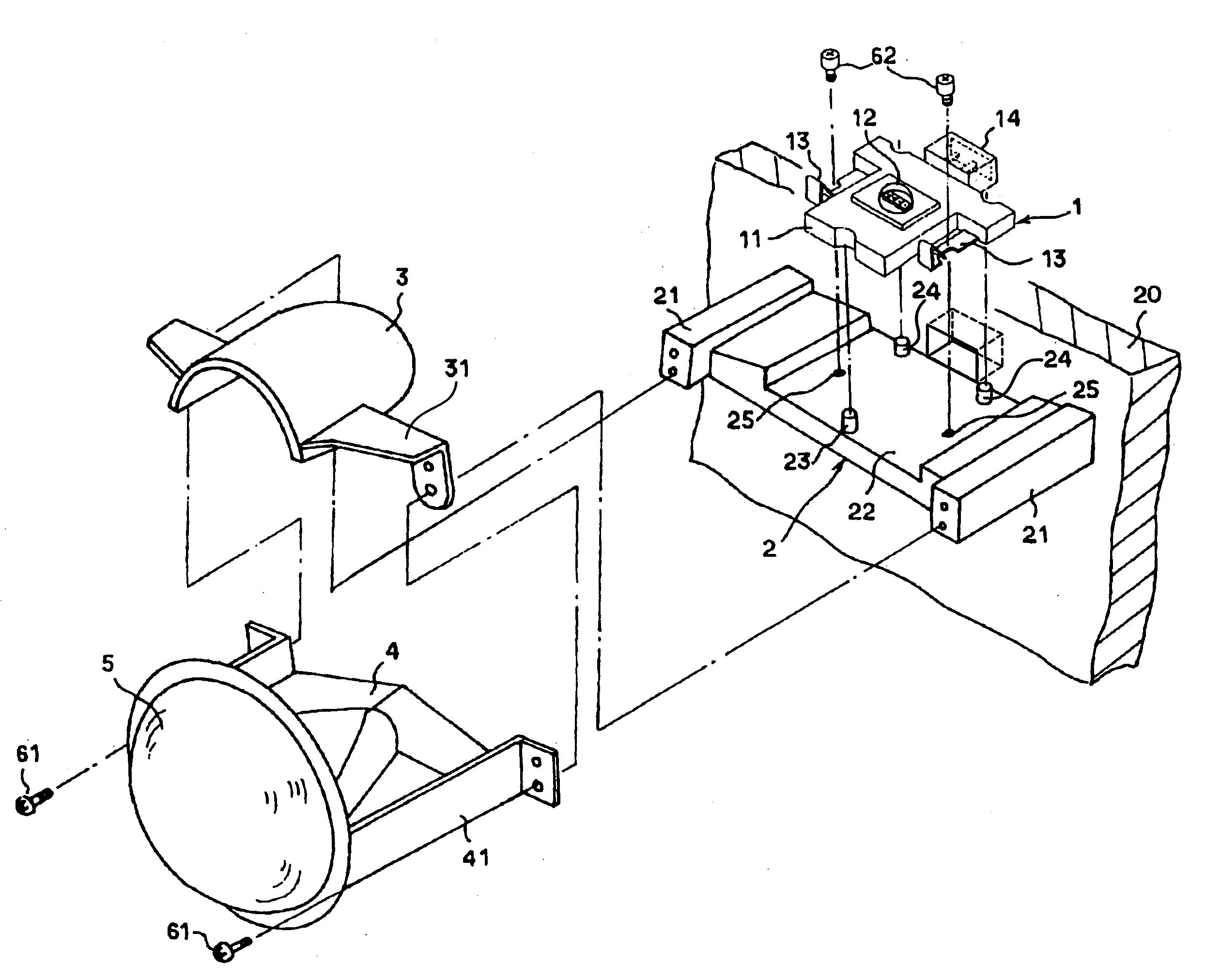
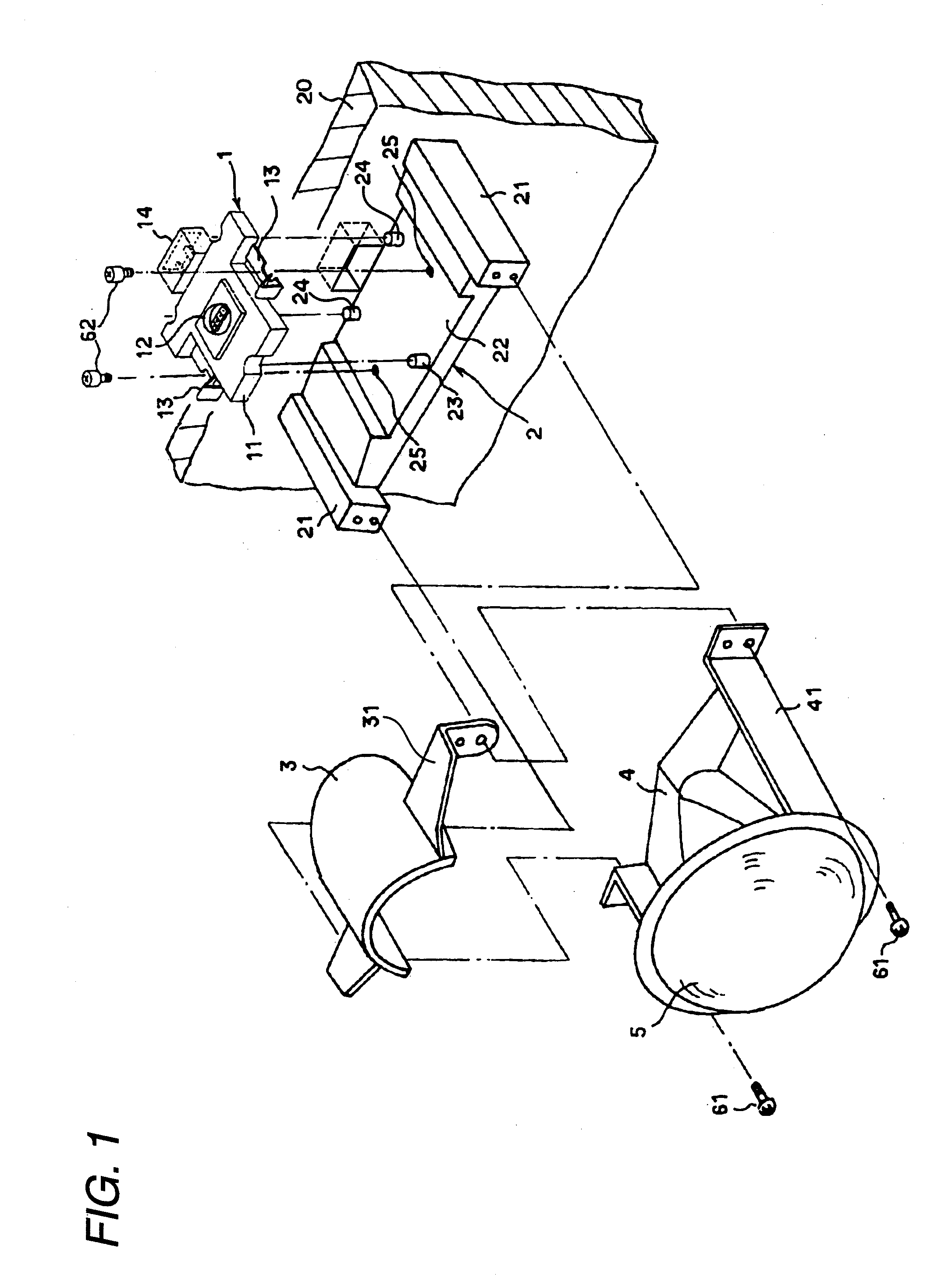
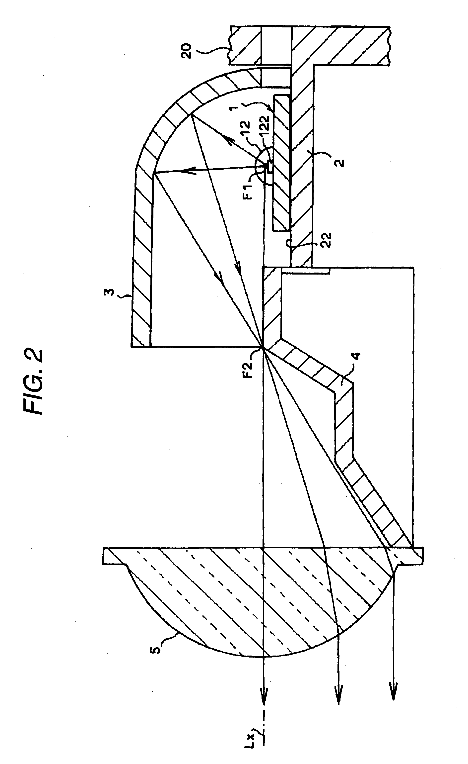
 are assigned like reference numerals. In the second exemplary embodiment, the LED package 12 is mounted at a position, on the module optical axis Mx and on the surface of the module substrate 11 made into the shape of a rectangular flat plate. Electric power is fed to the LED package 12 by way of the interconnection laid on the module substrate 11 and the connector 14, thereby illuminating the LED chips. An oblong reference hole 15 is opened at a front-side position on the module substrate 11 in the module optical axis Mx. A pair of screw insert holes 16 are opened at both positions that are behind the reference hole 15 and that have the module optical axis Mx sandwiched therebetween. As also can be seen in a cross-sectional structure of FIG. 9A, each of the screw insert holes 16 is made up of an u...


PUM


Abstract

A light source module is provided. The light source module includes a light emitting element; a module substrate on which the light emitting element is mounted; a support member comprising a position reference section; and a fixing member which fixes the module substrate to the support member. The module substrate includes a positioning section which determines a position of the module substrate; and a displacement force generation section which imparts a displacement force onto the module substrate so as to bring the positioning section into contact with the position reference section of the support member when the fixing member is fastened to the support member.

Description

BACKGROUND OF THE INVENTION[0001]1. Field of the Invention[0002]The present disclosure relates to a light source module having a light-emitting element, such as a light-emitting diode (LED), as a light source and that is suitable for use as a light source of a lamp fitting, such as an illuminating lamp of a vehicle.[0003]2. Description of Related Art[0004]In a recent vehicle, a related art lamp that uses a light-emitting element, such as an LED, as a light source element has been proposed in order to save energy expended in operation of the lamp when the lamp is used in head lamps and / or tail lamps. An example of such a related art lamp is described, for example, in Japanese Patent Unexamined Publication No. JP-A-2005-209537. In a lamp of this type, an LED is mounted, for example, on a power feeding substrate, and the substrate is implemented on a module substrate, to thus make up a light source module. Alternatively, an LED might be mounted directly on a module substrate, to form a...

Claims


Application Information

Patent Timeline
IPC IPC(8): F21V19/00
CPCF21Y2101/02F21V19/00F21Y2115/10F21S41/192
Inventor TSUKAMOTO, HIRONORI
Owner KOITO MFG CO LTD
Why Eureka
Try Eureka