
Safety switch on a peristaltic pump

a safety switch and peristaltic pump technology, applied in the field of peristaltic pumps, can solve the problems of internal leakage, tubing failure, small pinholes in the tubing, etc., and achieve the effect of facilitating tubing replacement and facilitating tubing replacemen

Active Publication Date: 2010-01-14
BLUE WHITE INDS
View PDF34 Cites 13 Cited by
  • Summary
  • Abstract
  • Description
  • Claims
  • Application Information

AI Technical Summary

Benefits of technology

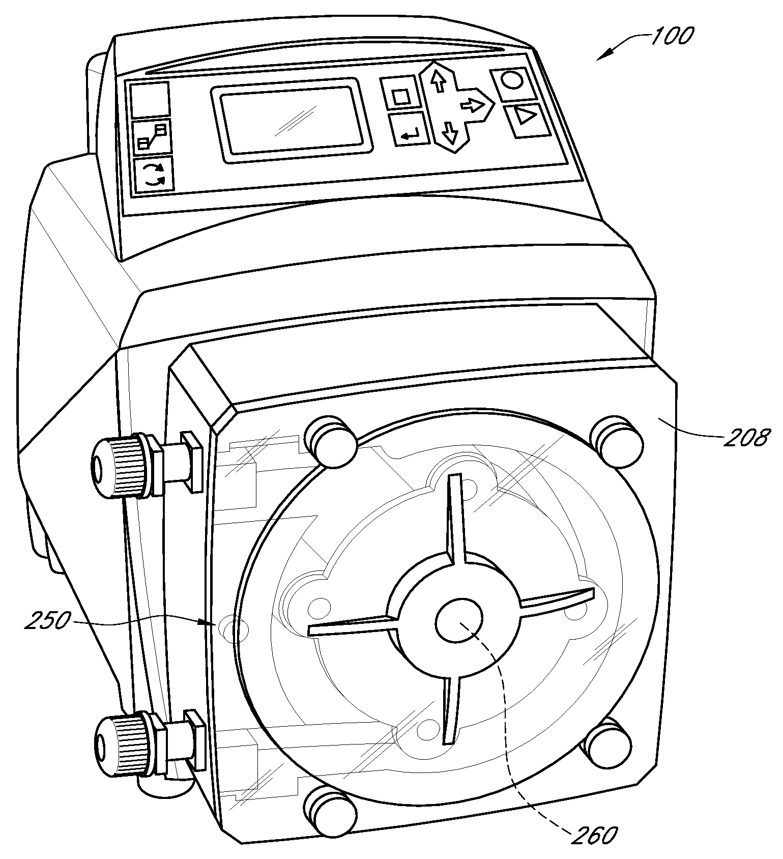
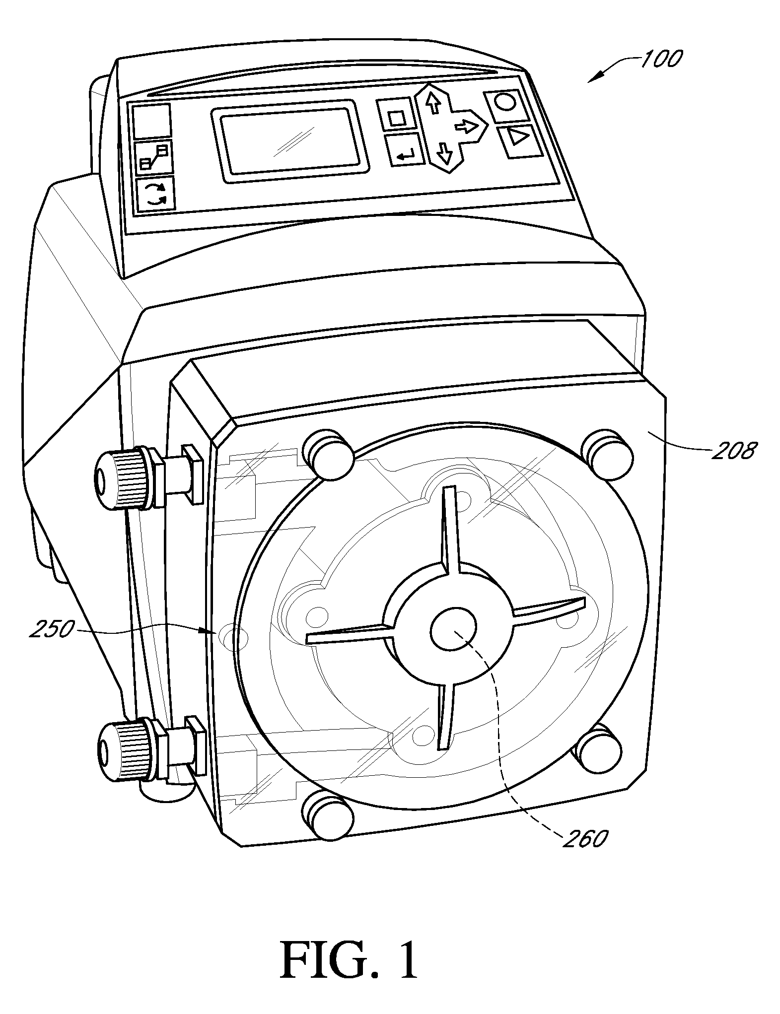
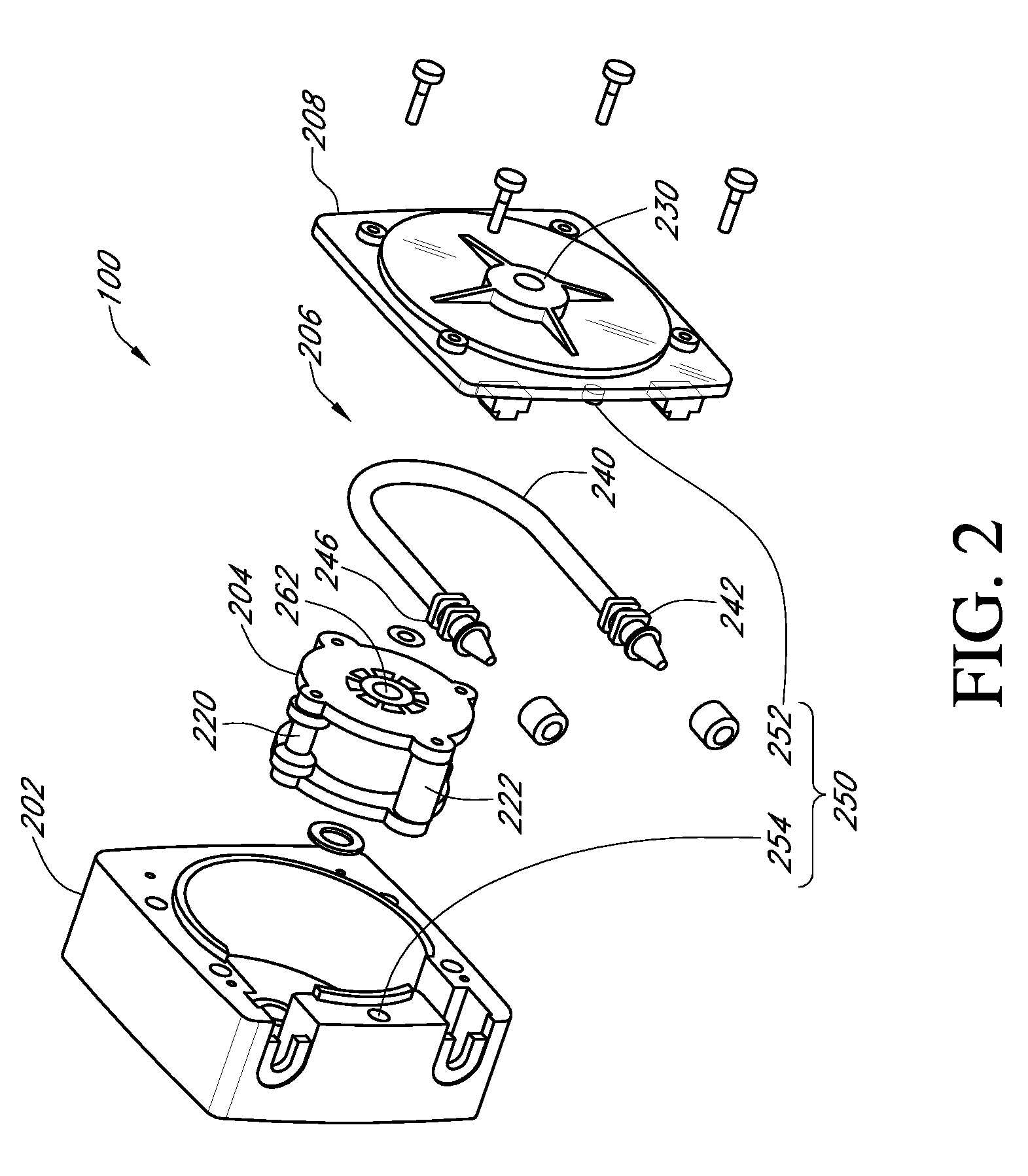
[0010]In accordance with another aspect of at least one of the embodiments disclosed herein is the realization that replacing tubing is facilitated if the rollers of a pump rotor are in motion. However, due to the usually high operating rpm of the rotor, the replacement of the tubing while the rotor is turning can be dangerous. Therefore, in some embodiments disclosed herein, a unique safety switch feature is provided that can be incorporated into the pump such that when a cover or panel of the pump is removed in order to replace the tubing, the pump is desirably permitted to operate only in a reduced rpm mode. In this manner, a user can benefit from a slow-moving rotor to facilitate replacement of the tubing without the danger of a fast-moving rotor.
[0019]In accordance with another embodiment, a peristaltic pump is provided for facilitating safe maintenance of the pump. The pump can comprise a pump head, a rotor disposed in an opening of the pump head, and a head cover that is mountable onto the pump head to extend across the opening in the pump head to cover the rotor. In this regard, when the pump is powered-on, the rotor rotates at an operational speed when the head cover is on the pump head and rotates at a slower speed when the head cover is off the pump head.

Problems solved by technology

Over time, the high pressures at the pump outlet can wear on the tubing and result in the development of small pinholes in the tubing.
If unnoticed, the pinholes can grow and eventually result in failure of the tubing.
Ruptured tubing can lead to internal leakage and the cessation of proper function.
When the pump is used to move a corrosive chemical, such as chlorine, internal leakage can be particularly hazardous.
As the chemical comes into contact with the pump components, the pump may become irreparably damaged.
This is a serious shortcoming because the costs associated with replacement of the pump can be very substantial.
When tubing is replaced, the placement of the tubing underneath the rollers of the pump can be a very difficult task, especially in industrial applications.
This task is extremely difficult considering the narrow spacing between the rollers and the pump wall.
However, due to the usually high operating rpm of the rotor, the replacement of the tubing while the rotor is turning can be dangerous.

Method used


Image

  • Safety switch on a peristaltic pump
  • Safety switch on a peristaltic pump
  • Safety switch on a peristaltic pump

Examples


Embodiment Construction

[0024]While the present description sets forth specific details of various embodiments, it will be appreciated that the description is illustrative only and should not be construed in any way as limiting. Furthermore, various applications of such embodiments and modifications thereto, which may occur to those who are skilled in the art, are also encompassed by the general concepts described herein.

[0025]Moreover, although not discussed at length herein, related embodiments of a tubing installation tool are disclosed in applicant's copending patent application, U.S. patent application Ser. No. ______, filed on ______, entitled TUBING INSTALLATION TOOL FOR A PERISTALTIC PUMP AND METHODS OF USE, the entirety of the disclosure of which is incorporated herein by reference. Further, related embodiments of a method for extending tubing life of a tubing assembly of a peristaltic pump are disclosed in applicant's copending patent application, U.S. patent application Ser. No. ______, filed on...


PUM

PropertyMeasurementUnit
Angular velocityaaaaaaaaaa

Abstract

A peristaltic pump is provided that is configured to facilitate safe maintenance of the pump. The pump can comprise a pump body having a pump head and a head cover and a safety switch mechanism. The safety switch mechanism can comprise one or more sensors that allow the pump to detect whether the head cover is in an open or closed position. When the pump is powered-on, the pump can be configured to enter a maintenance mode when the safety switch detects that the head cover is in the open position.

Description

CROSS-REFERENCE TO RELATED APPLICATIONS[0001]This application claims the benefit of U.S. Provisional Application No. 61 / 080,642, filed Jul. 14, 2008, the entirety of the disclosure of which is incorporated herein by reference.BACKGROUND[0002]1. Field of the Inventions[0003]The present inventions relate generally to peristaltic pumps. More particularly, the present inventions relate to a uniquely-configured peristaltic pump that can include a maintenance mode for facilitating safe replacement of pump tubing.[0004]2. Description of the Related Art[0005]A peristaltic roller pump typically has three or more rollers, but may have other configurations. The rollers are spaced circumferentially evenly apart and are mounted on a rotating carrier that moves the rollers in a circle. A length of flexible tubing is placed between the rollers and a semi-circular wall. In medical applications, the tubing can be a relatively soft and pliable rubber tubing. For relatively high pressure industrial ap...

Claims


Application Information

Patent Timeline
IPC IPC(8): F04B49/02F04B43/12
CPCB25B33/00Y10T29/49238Y10T29/49236Y10T29/4924Y10T29/53952
Inventor MCDOWELL, WILLIAM M.NGUYEN, JOHNGLEDHILL, ROBERT E.
Owner BLUE WHITE INDS
Learn More