
Sprocket assembly

a technology for sprockets and components, applied in mechanical devices, transportation and packaging, hoisting equipment, etc., can solve the problems of easy fatigue of structure parts, a lot of burden on the fastening portion, etc., and achieve the effect of preventing structure fatigue and improving structure strength

Inactive Publication Date: 2010-01-14
TIEN HSIN INDS
View PDF59 Cites 58 Cited by
  • Summary
  • Abstract
  • Description
  • Claims
  • Application Information

AI Technical Summary

Benefits of technology

[0009]Each of the first fastening bores has a corresponding first bore aligning therewith and the first sprocket is fixed on a first surface of the supporter. Each of the second fastening bores has a corresponding second bore aligning therewith and the second sprocket is fixed on a second surface of the supporter. Therefore, the first fastening bores separately support the power from the first sprocket and the second fastening bores separately support the power from the second sprocket. From the point of view of the connecting rigidity, the present invention provides a better structure strength than those of the prior art in which the sprockets are fixed in the different fastening bores of the supporter for preventing the structure fatigue from arising.

Problems solved by technology

However, it burdens with the fastening portion a lot that the two sprockets respectively and co-axially fixed on the two opposite sides of the fastening portion.
Therefore, a structure fatigue will be easily happened when the single fastening portion is alternately driven by two sprockets.

Method used


Image

  • Sprocket assembly
  • Sprocket assembly
  • Sprocket assembly

Examples


Embodiment Construction

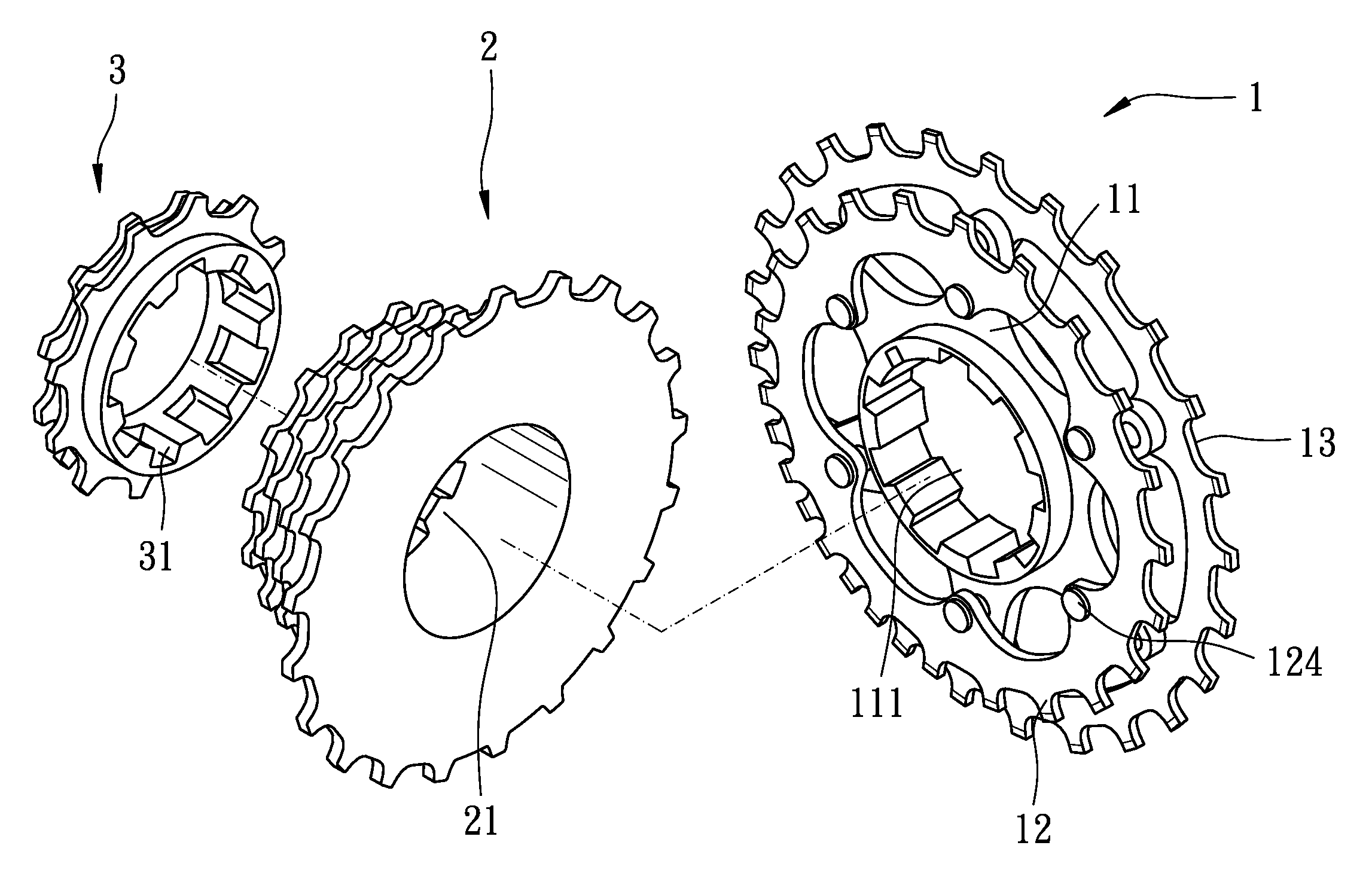
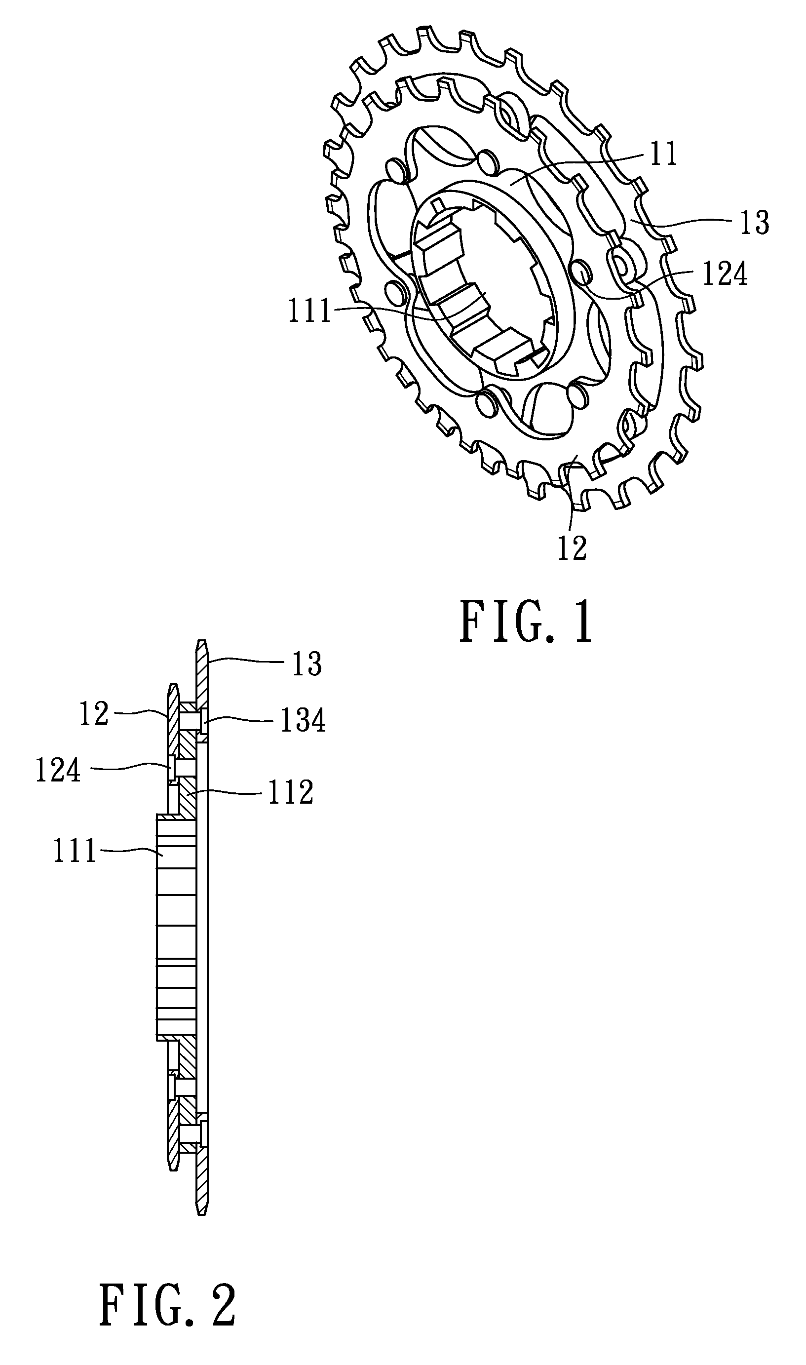
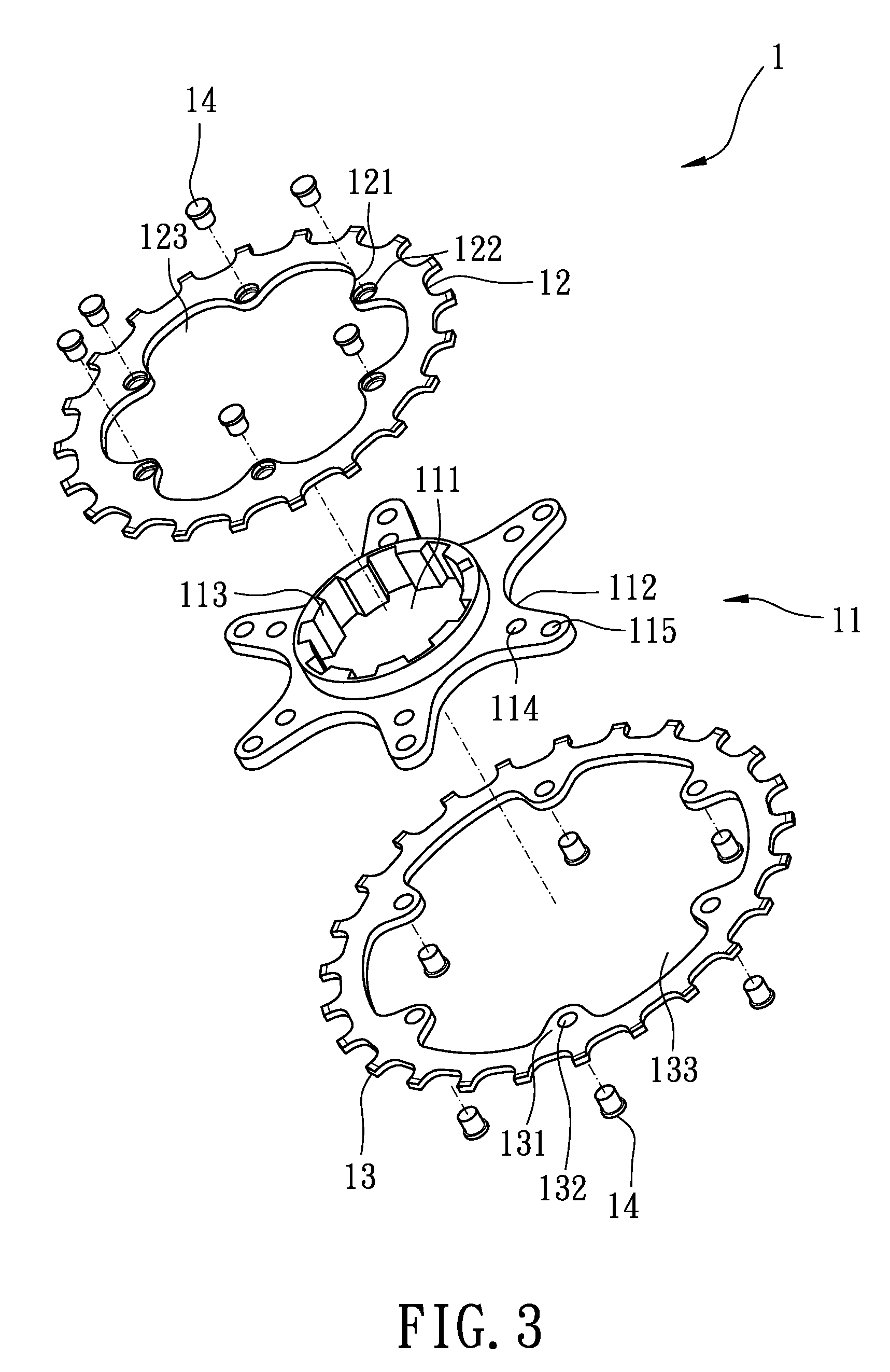
[0016]Referring to the drawings and initially to FIGS. 1-3, a sprocket assembly in accordance with the present invention comprises a first sprocket set (1) including a first sprocket (12), a second sprocket (13) and a supporter (11) for co-axially combining the first sprocket (12) and the second sprocket (13).

[0017]The first sprocket (12) has a first series of teeth radially and outwardly extending therefrom, and selectively meshed by a chain of a bicycle. The first sprocket (12) has a hole (123) centrally defined therein and extending therethrough, and multiple first protrusions (121) radially inwardly extending from an inner periphery of the hole (123) in the first sprocket (12). Each of the multiple first protrusions (121) has a first bore (122) defined therein and each of the first bores (122) is adjacent to the hole (123) of the first sprocket (12).

[0018]The second sprocket (13) has a structure similar to the first sprocket (12). The second sprocket (13) has a second series of ...


PUM


Abstract

A sprocket assembly includes a first sprocket set having multiple first bores defined therein. A second sprocket has multiple second bores defined therein. A supporter has multiple first fastening bores defined therein and multiple second fastening bores defined therein. The first sprocket and the second sprocket are respectively fixed on two opposite sides of the supporter. Each of the first protrusions is fixed on a corresponding one of the first fastening bores. Each of the second protrusions is fixed on a corresponding one of the second fastening bores.

Description

BACKGROUND OF THE INVENTION[0001]1. Field of the Invention[0002]The present invention relates to a sprocket assembly, and more particularly to a sprocket assembly for a bicycle.[0003]2. Description of Related Art[0004]A conventional bicycle sprocket assembly has at least one subassembly including a sprocket support member and two sprockets. The support member has at least one engagement portion for coupling it to a bicycle freewheel and at least one fastening portion arranged in a radially external position with respect to the engagement portion. Both sprockets are fixed on the sprocket support member on two opposite sides of the fastening portion.[0005]The two sprockets of the conventional bicycle sprocket assembly are fastened on the sprocket support member and connected to the bicycle freewheel. The two sprockets of the conventional bicycle sprocket assembly are respectively fixed on a corresponding one of two sides of the sprocket member and at least one fastener co-axially fixe...

Claims


Application Information

Patent Timeline
Patent Type & Authority Applications(United States)
IPC IPC(8): B62M9/10F16H55/30
CPCB62M9/10
Inventor CHIANG, DOUGLAS
Owner TIEN HSIN INDS
Features
  • Generate Ideas
  • Intellectual Property
  • Life Sciences
  • Materials
  • Tech Scout
  • Unparalleled Data Quality
  • Higher Quality Content
  • 60% Fewer Hallucinations
Learn More