
Temperature-compensated in-vivo sensor

a sensor and temperature compensation technology, applied in the field of medical devices, can solve the problems of inaccurate analyte measurements, inability to accurately measure body temperature, and risk of contamination by infusion process, and achieve the effect of slowing down certain autonomic responses, accurate analyte measurements, and fluctuation of body temperatur

Inactive Publication Date: 2010-01-14
SANVITA MEDICAL CORPORATION
View PDF33 Cites 6 Cited by
  • Summary
  • Abstract
  • Description
  • Claims
  • Application Information

AI Technical Summary

Benefits of technology

[0027]Another major advantage of the present invention is the inclusion of a temperature sensor for obtaining accurate analyte measurements. Biosensors are intrinsically sensitive to temperature. Relatively small changes in temperature can affect measurement results on the order of 3-4% per degree Celsius. Many clinical procedures benefit from tight glycemic control provided by an in-vivo continuous glucose monitoring (CGM) sensor. During these procedures, body temperature can fluctuate. In fact, many procedures involve dropping the core body temperature significantly. For example, it is customary during certain invasive thoracic procedures to “ice down” patients from 37° Celsius down to 25-30° Celsius. This induced hypothermia procedure intentionally slows certain autonomic responses. A sensor that is stable and calibrated at a body core temperature of 37° Celsius, is no longer calibrated nor accurate during such a procedure.
[0028]For CGM applications where the sensor is subcutaneously implanted approximately 5 to 8 millimeters into the abdomen (or other alternative locations), temperature changes can also have an adverse effect on system accuracy. Subcutaneous CGM patients are more likely healthy and highly mobile patients who may be moving in a changing variety of indoor and outdoor weather conditions. All of this may greatly affect the temperature at which the sensor is operating and, consequently, affecting the precision of the measurement readings that the sensor provides.
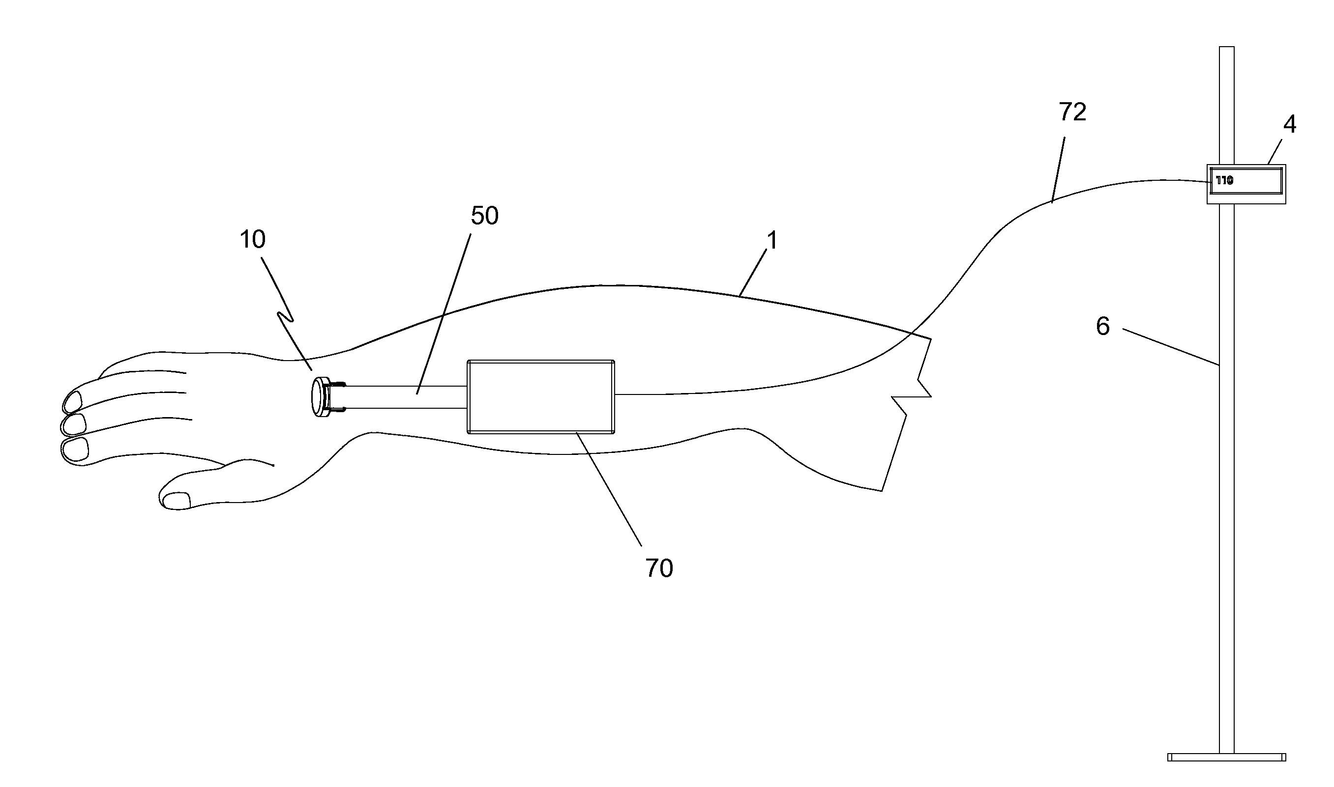
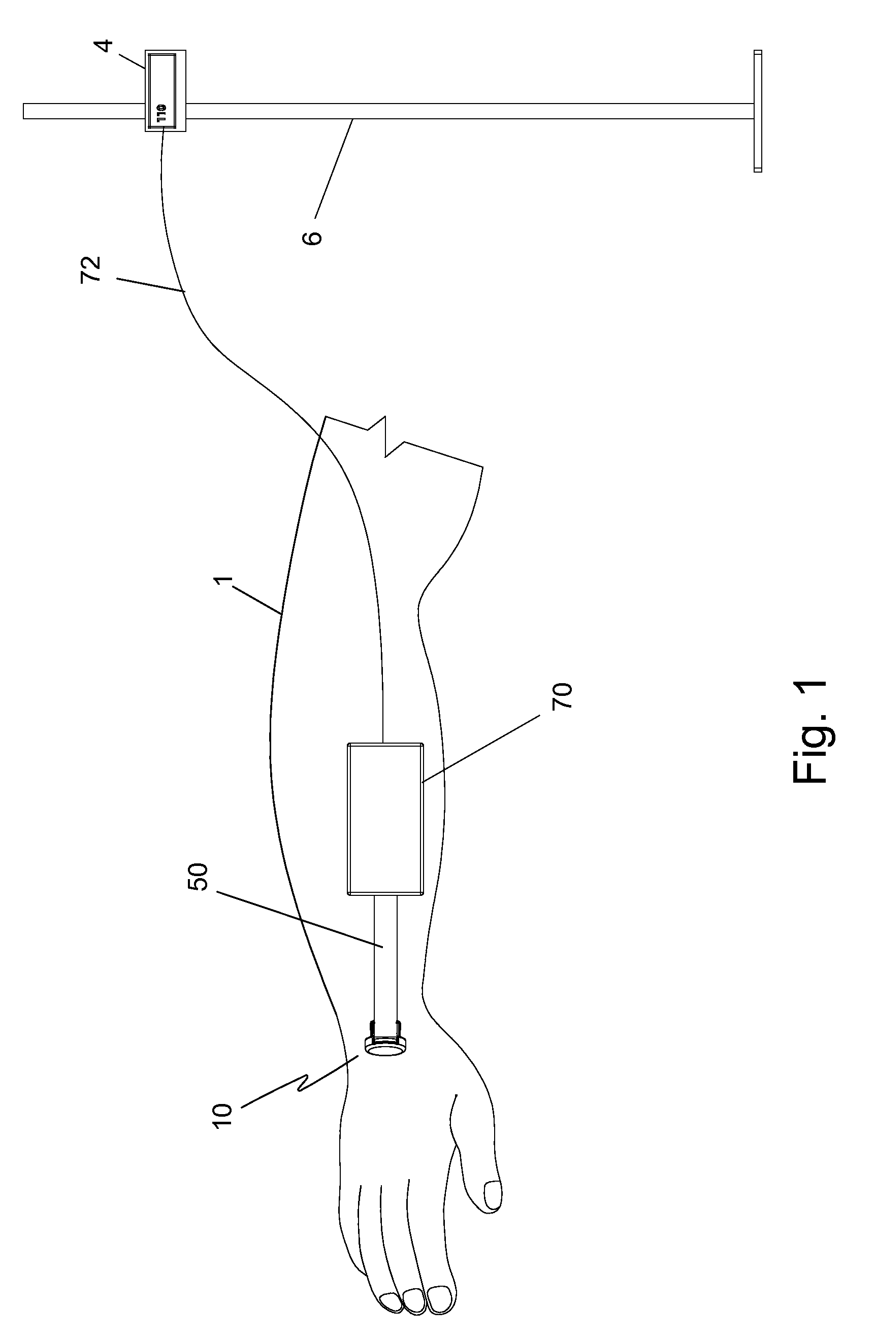
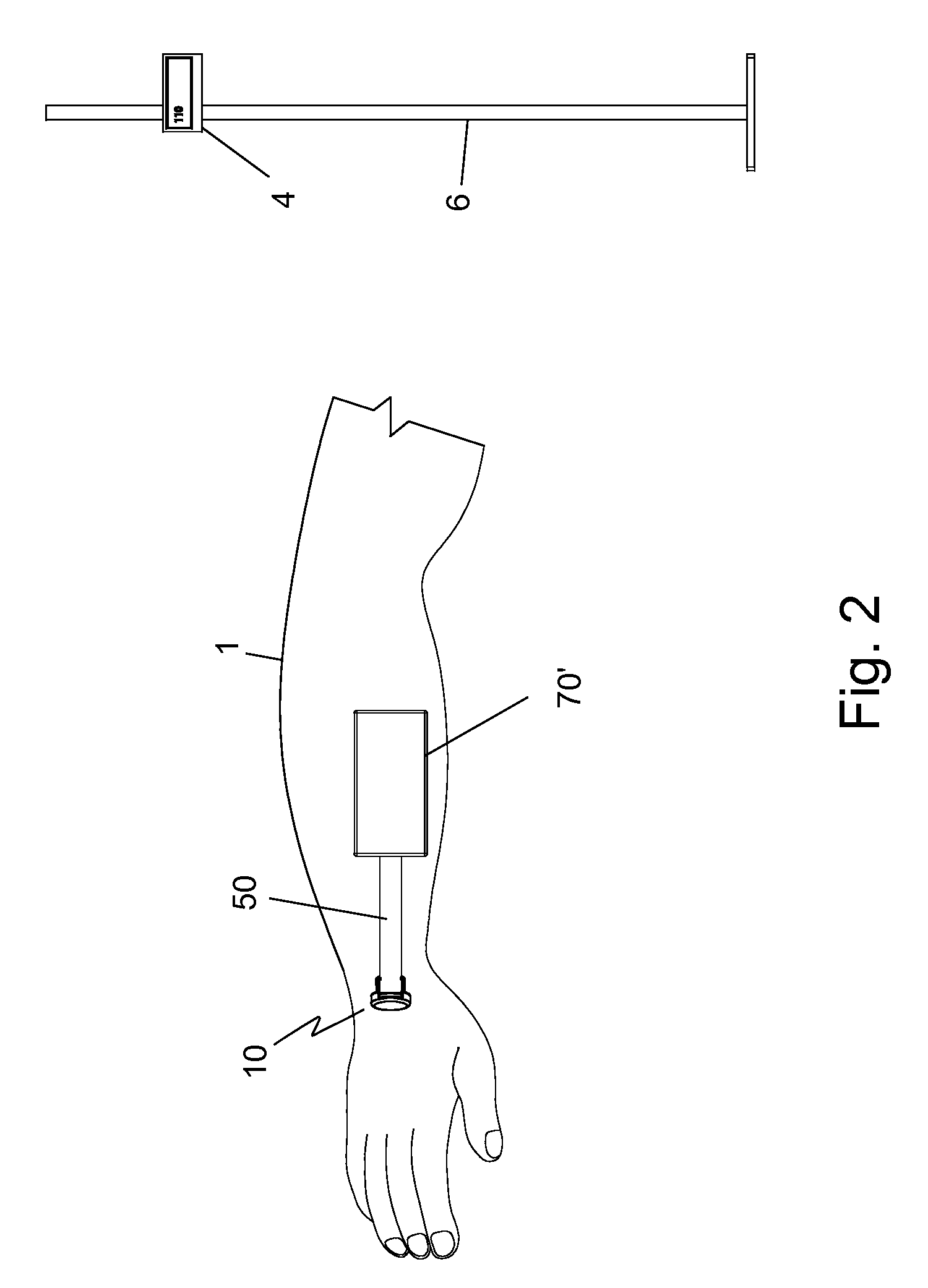
[0029]By placing a temperature sensing element in exact proximity to the biosensor in the blood flow for intravascular applications and in the tissue for subcutaneous applications, the temperature effect on the biosensor can be measured and the biosensor output can be properly compensated to reflect an accurate analyte concentration. An RTD sensor, preferably a platinum RTD, with a temperature accuracy of 0.1° C. is configured at the distal end of the sensor sheath. In fact, maintaining the temperature sensor within 0.25 mm of the analyte sensor greatly improves overall accuracy of the system.
[0030]In a further embodiment of the present invention, the analyte sensor element includes a analyte-selective reagent matrix having a plurality of layers where one of the plurality of layers contains an enzyme that is a substrate of the analyte to be measured and another layer disposed over the layer containing the enzyme that is a composite layer having a plurality of microspheres disposed in a hydrogel. The plurality of microspheres are made of a material having substantially little or no permeability to the analyte and substantially high permeability to oxygen while the hydrogel is made of a material that is permeable to the analyte. The material of the microspheres is preferably polydimethylsiloxane and the hydrogel is preferably one of polyurethane or poly-2-hydroxyethyl methacrylate (PHEMA). In another embodiment, the layer containing the enzyme is a PHEMA layer.
[0031]In still another embodiment of the present invention, the reagent matrix on the analyte sensor includes a hydrogel layer disposed on the composite layer. This hydrogel layer may optionally include a catalase. The hydrogel is preferably one of polyurethane or PHEMA.
[0032]In a further embodiment of the present invention, the reagent matrix on the analyte sensor includes a semi-permeable layer disposed between the composite layer and the electrically conductive electrode(s) of the analyte sensor.

Problems solved by technology

A problem encountered in reversing an infusion line for sampling is determining how much blood should be withdrawn in order to be certain that pure, undiluted blood is in contact with the sensor.
Although Levin discloses a method of halting the withdrawal of blood at the proper time so that a pure, undiluted sample is presented to the sensor, the method uses an expensive sensor and risks the possibility of contamination by the infusion process.
If the temperature of the surroundings changes, an error occurs in the measurement.
Thus, a change in temperature of the surroundings causes an error in the computed analyte level.
A disadvantage of these approaches is that they focus on the magnitude of measurement errors and do not distinguish those errors that would be clinically significant in the management of a disease such as diabetes.
Zone C represents measurements deviating from the reference glucose level by more than 20% and would lead to unnecessary corrective treatment errors.
Zone D represents measurements that are potentially dangerous by failing to detect and treat blood glucose levels outside of the desired target range.
However, these statistics do not adequately describe and may give inflated notions of the true accuracy of a glucose / analyte sensor.
Currently analysis methods for accuracy of continuous glucose sensors focus on “point-by-point” assessments of accuracy and may miss important temporal aspects to the data.

Method used


Image

  • Temperature-compensated in-vivo sensor
  • Temperature-compensated in-vivo sensor
  • Temperature-compensated in-vivo sensor

Examples


example 1

[0131]An example of experimental data with and without temperature correction using one embodiment of the present invention is illustrated in FIG. 27. In this in-vitro example, a glucose sensor is exposed to a variety of glucose concentrations while at the same time the temperature of the environment is altered. The glucose concentrations are depicted in FIG. 27 adjacent the measurement traces.

[0132]Temperature is depicted on the right axis and shows an initial temperature of approximately 33° C. until approximately 80 minutes into the test. Thereafter, the temperature is gradually raised to 37° C. After equilibrating at this new temperature point, the temperature is raised to 41° C. where it remains for approximately 60 minutes and then allowed to cool gradually. At the same time the temperature is altered, the sensor is exposed to several glucose concentrations (ranging from 39.2 mg / dl to 323.1 mg / dl), and the response of the glucose sensor is recorded. Glucose concentration is pr...

example 2

[0133]Even small fluctuations in temperature can result in glucose measurement variability and should be corrected if one is to present accurate glucose data to the user. In FIG. 28, there is illustrated data obtained from an in-vitro test when a glucose sensor of the present invention having an integrated temperature sensor is placed in a vial of known glucose concentration and monitored for 5 days. The vial contained an aqueous standard solution having a glucose concentration of 280 mg / dl. Small fluctuations in room temperature are recorded by the temperature sensor and are also reflected in the performance of the glucose sensor. As shown by the data, small temperature fluctuations cause relatively large sensor reading fluctuations, which provides inaccurate concentration readings. By using temperature correction algorithms along with placement of the temperature sensor within 0.25 mm or closer to the enzyme measuring electrode, the temperature sensor data can be used to correct t...


PUM


Abstract

A reagent matrix composition disposed on an electrically conductive electrode to form an in-vivo sensor for a predefined analyte includes a first hydrogel layer containing an enzyme that is a substrate for the analyte adjacent the electrically conductive electrode and a composite membrane layer disposed onto the first hydrogel layer where the composite layer includes a membrane hydrogel containing a plurality of microspheres. The plurality of microspheres is made of a material having no or little permeability to the analyte and a substantially high permeability to oxygen.

Description

[0001]This application is a Continuation of Ser. No. 12 / 503,376, filed on Jul. 15, 2009, which is a Continuation-in-Part Application of Ser. No. 12 / 052,985, filed on Mar. 21, 2008.BACKGROUND OF THE INVENTION[0002]1. Field of the Invention[0003]The present invention relates generally to the field of medical devices. Particularly, the present invention relates to devices and methods for placing a sensor at a selected site within the body of a patient. More particularly, the present invention relates to a temperature-compensated in-vivo sensor and an insertion set therefor.[0004]2. Description of the Prior Art[0005]In the past, it was discovered that tight glycemic control in critically ill patients yielded statistically beneficial results in reducing mortality of patients treated in the intensive care unit for more than five days. A study done by Greet Van den Berghe and associates (New England Journal of Medicine, Nov. 8, 2001) showed that using insulin to control blood glucose withi...

Claims


Application Information

Patent Timeline
Patent Type & Authority Applications(United States)
IPC IPC(8): A61B5/00
CPCA61B5/14532A61B5/14865A61B2560/0252A61B5/6848A61B5/1495
Inventor JOBST, GERHARD
Owner SANVITA MEDICAL CORPORATION
Learn More