Apparatus And Method For The Detection Of Forces In The Sub-Micronewton Range

Inactive Publication Date: 2010-01-14
TECH UNIV MUNCHEN
View PDF3 Cites 44 Cited by
  • Summary
  • Abstract
  • Description
  • Claims
  • Application Information

AI Technical Summary

Benefits of technology

[0023]Further, the difference between the level of the force plateau associated with the carrier and the force plateau associated with the probe element can be evaluated for determining the adhesion of the probe elemen

Problems solved by technology

Here, two problems occur.
On the one hand, the tip is after a short time not usable anymore, because the reactive groups are saturated.
A further great problem with conventional methods consists in discerning the intramolecular forces to be measured from unspecific interactions, in particular from interactions between the measuring tip and the surface to be measured.
Moreover, this method could only be d

Method used


Image

  • Apparatus And Method For The Detection Of Forces In The Sub-Micronewton Range
  • Apparatus And Method For The Detection Of Forces In The Sub-Micronewton Range
  • Apparatus And Method For The Detection Of Forces In The Sub-Micronewton Range

Examples


Example

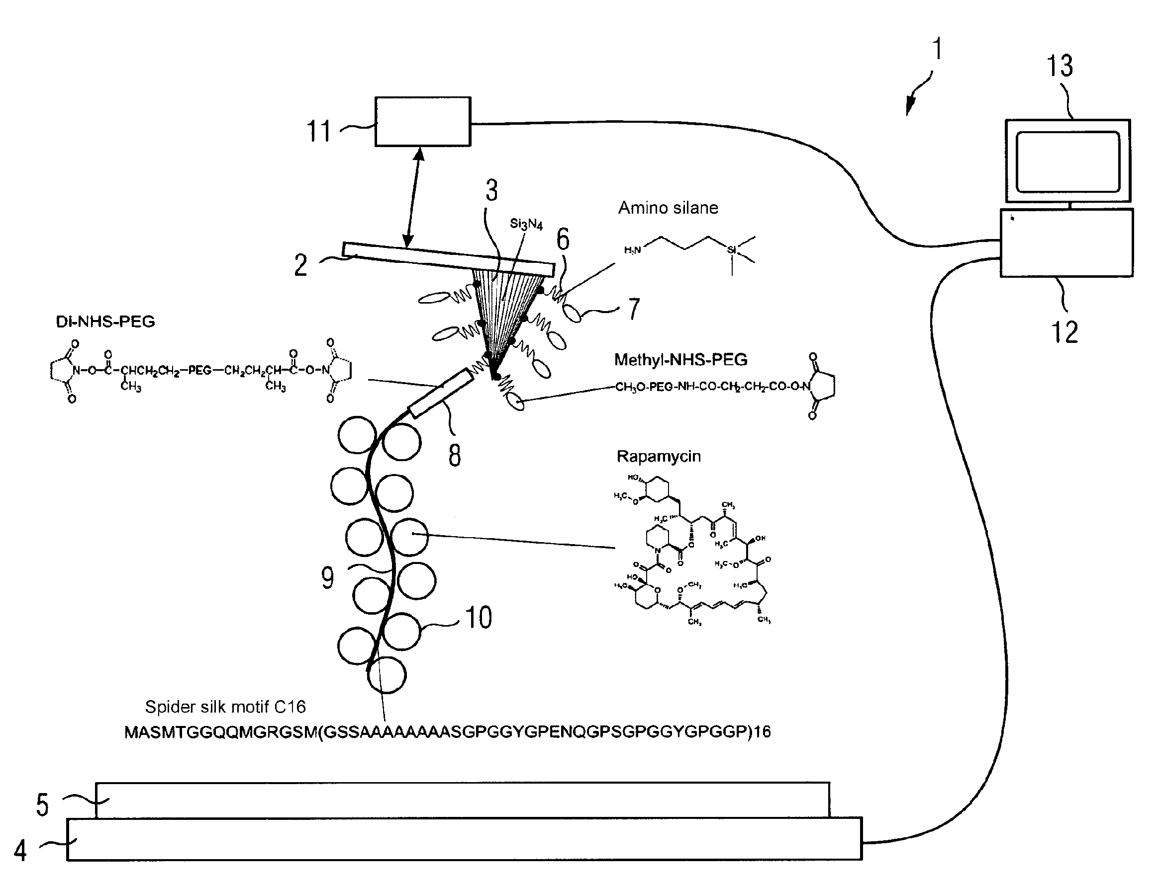
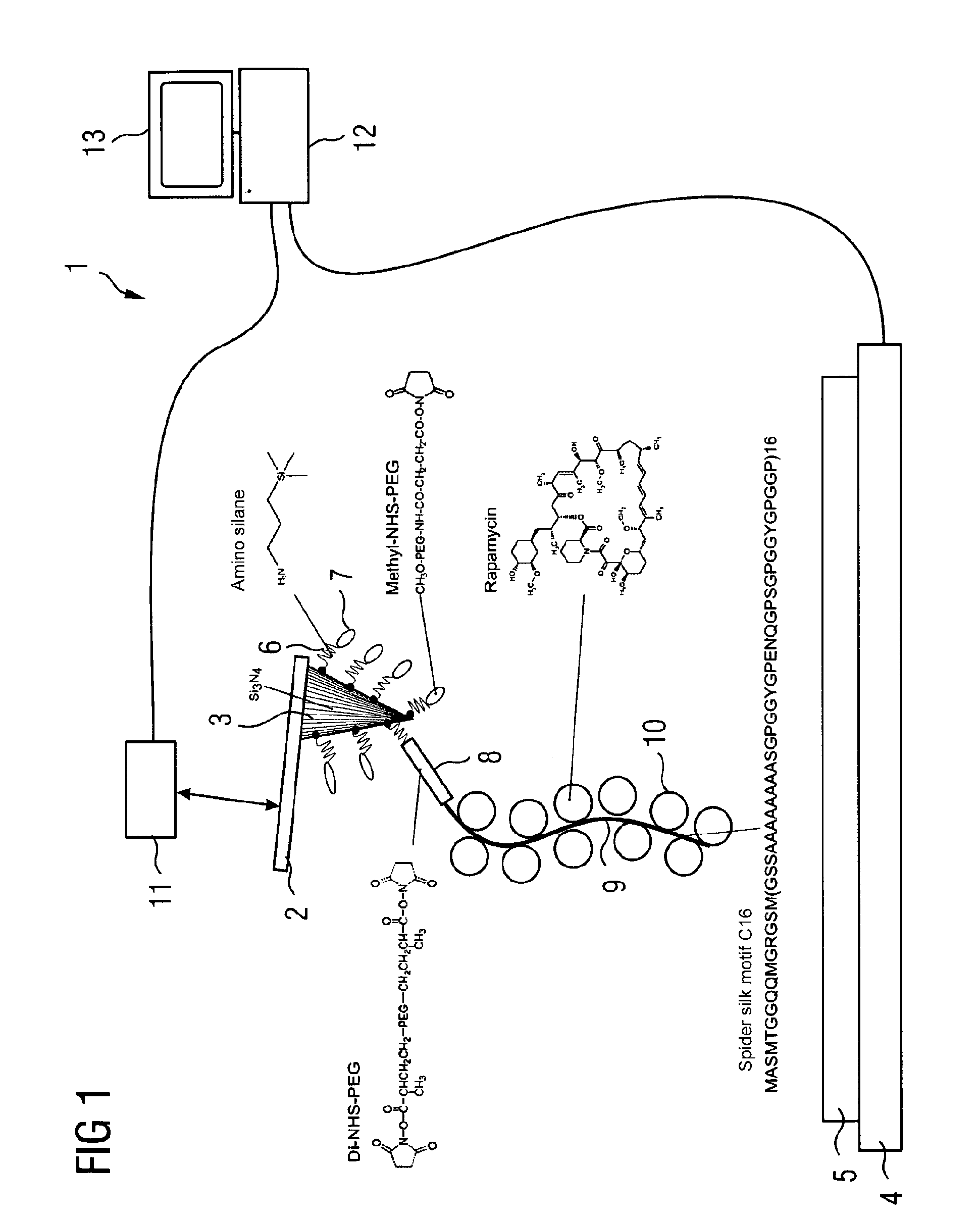
[0031]FIG. 1 shows an atomic force microscope 1 which comprises a measuring tip 3 attached to a cantilever 2. The atomic force microscope 1 further comprises a sample holder 4 on which is arranged a sample 5.

[0032]The measuring tip 3 is coated with activating molecules 6, which, for instance, may be amino silane as shown in FIG. 1. The free ends of the activating molecules are connected to passivating molecules 7 and connecting molecules 8. The connecting molecules 7 may, for instance, be methyl-NHS-PEG which has at its free end a methyl end group. On the contrary, the connecting molecules 8 are Di-NHS-PEG which have at both ends a succinimidyl end group. To the connecting molecule 8 can be attached a carrier molecule 9, for which, for instance, a synthesized spider silk can be used, in particular the spider silk motif C16. The length of the carrier molecule is typically less than 5 nm. Laterally attached to the carrier molecule 9 are probe molecules 10, for instance an agent molecu...


PUM


Abstract

A force microscope for the detection of forces in the sub-micronewton range has a measurement head which is used to carry out a relative movement with respect to a sample holder and to which a carrier molecule is attached on which probe molecules are placed.

Description

CROSS-REFERENCE TO RELATED APPLICATIONS[0001]The present application is a continuation of pending International patent application PCT / EP2008 / 050075 filed on Jan. 5, 2008, which designates the United States and claims priority of German Application No. 10 2007 001 797 filed on Jan. 5, 2007. The disclosure of this application is hereby incorporated by reference in its entirety, as part of the present disclosure.FIELD OF THE INVENTION[0002]The invention relates to an apparatus for the detection of forces in the sub-micronewton range with a measuring head with which a relative movement in relation to a sample holder can be carried out and to which at least one probe element is attached by which an adhesion force between a sample placed on the sample holder and the measuring head can be transferred.[0003]Further the invention relates to a method for the detection of forces in the sub-micronewton range.BACKGROUND OF THE INVENTION[0004]Such an apparatus and such a method are known from EP...

Claims


Application Information

Patent Timeline
IPC IPC(8): G01N13/10G12B21/02G01Q30/04G01Q60/42
CPCB82Y35/00G01N33/54373G01Q60/42G01Q60/28G01Q30/04
Inventor HUGEL, THORSTENGEISLER, MICHAEL
Owner TECH UNIV MUNCHEN
Why Eureka
Try Eureka