
Roof and wall covering with improved corner construction

Active Publication Date: 2010-01-21
NOVIK INC
View PDF22 Cites 13 Cited by
  • Summary
  • Abstract
  • Description
  • Claims
  • Application Information

AI Technical Summary

Benefits of technology

[0006]It is an object of the present invention to provide a wall covering having corner moldings that facilitate more reliable installation and which are adapted for long-term usage.
[0007]Another object is to provide a corner molding of the foregoing type which permits efficient mounting of the corner moldings after installation of the wall panels.

Problems solved by technology

Installation problems particularly occur when installing such synthetic wall and roof coverings about comers of the roof or sidewalls.
Such mounting requires precise cutting of the ends of the panels to ensure good installation, which can substantially increase the time and cost of installation.
In other known corner moldings, an end of the wall panel is positioned into a side cavity of the corner molding, which can leave unsightly gaps between the corner molding and wall panel by virtue of excessive tolerances.
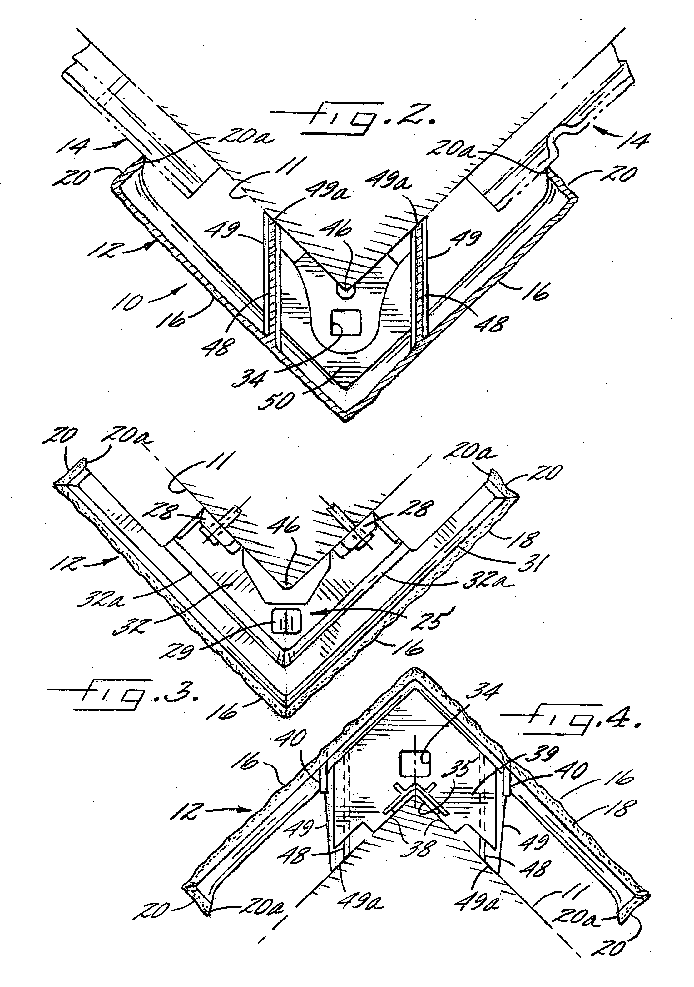
While it is desirable to provide internal vertical support and reinforcing walls that extend inwardly of the front faces of such corner moldings, a problem with such internal walls or reinforcing flanges in plastic injection molded parts is that they can create sink marks on the exposed outer faces of the corner molding due to non-uniform cooling of the molded plastic material at the juncture between the mating walls.
Vertical sink marks are a particular problem with corner moldings which have horizontally disposed building elements, typical of simulated hand laid stone or brick.

Method used


Image

  • Roof and wall covering with improved corner construction
  • Roof and wall covering with improved corner construction
  • Roof and wall covering with improved corner construction

Examples


Embodiment Construction

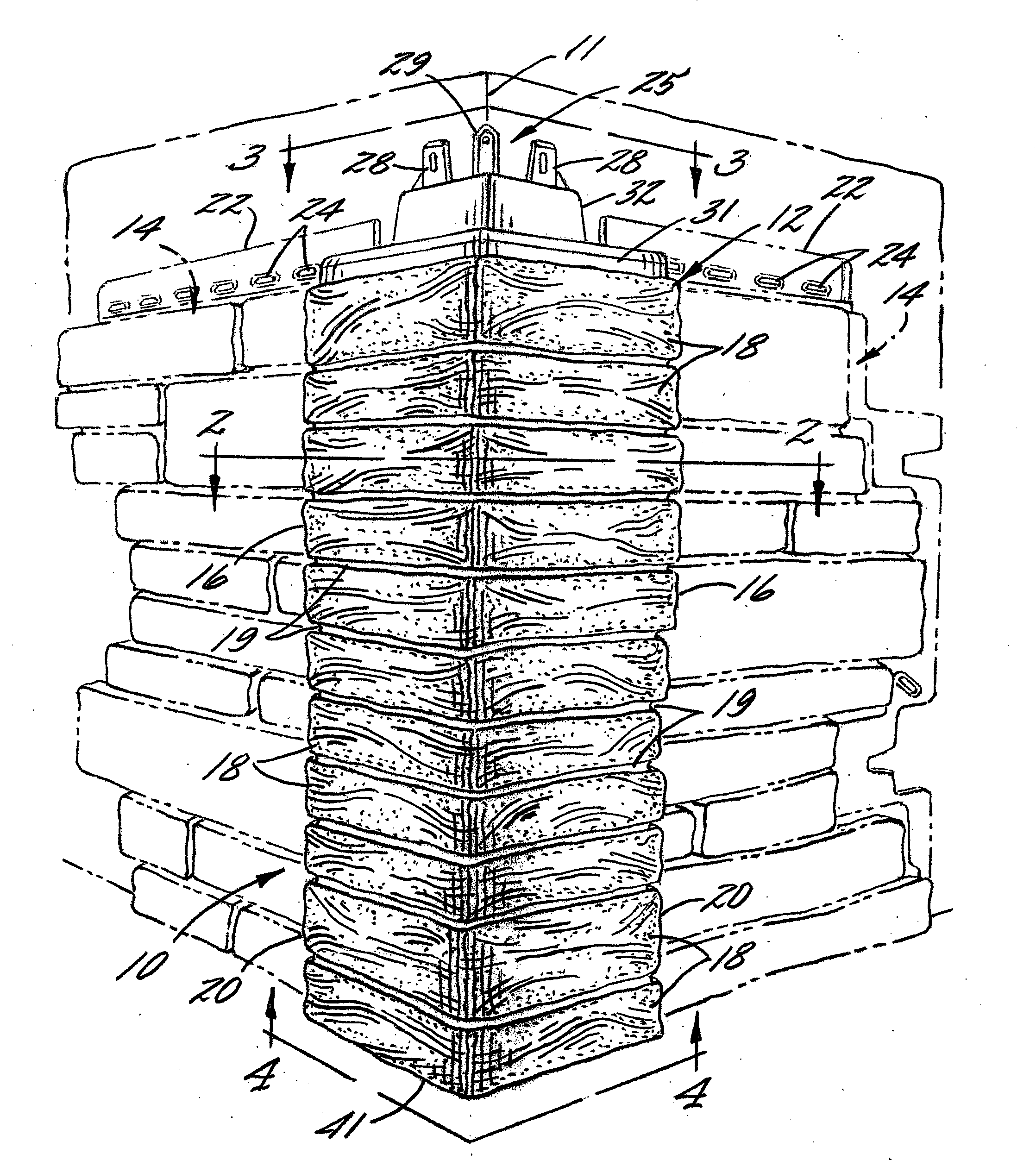
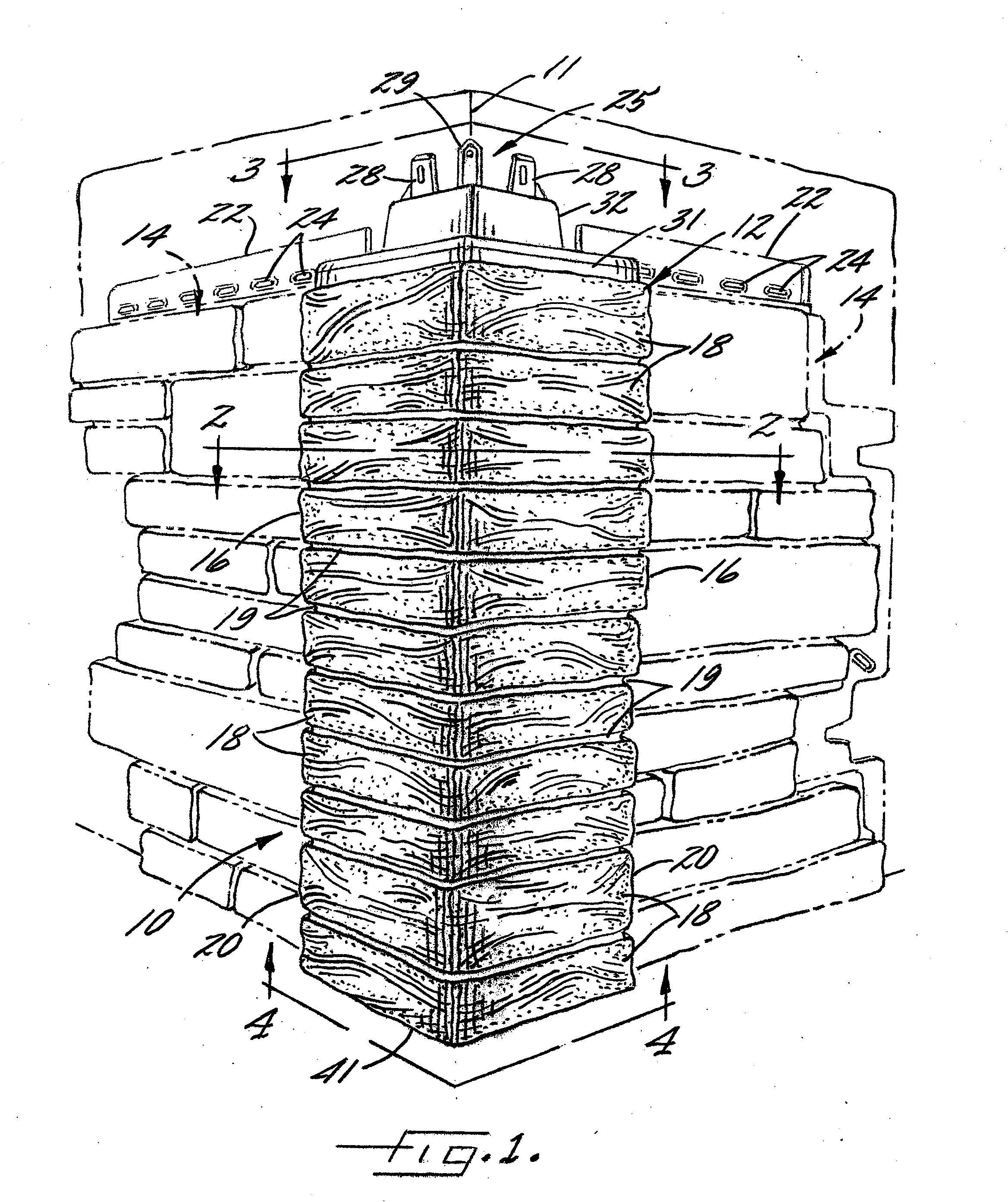
[0016]Referring now more particularly to the drawings, there is shown an illustrative wall covering 10 in accordance with the invention mounted about a corner of sidewall surfaces 11 of a building structure. The wall surfaces 11 in this case are at a right angle to each other typical of the exterior corner of a building. The wall covering 10 comprises a plurality of corner moldings 12 mounted in vertically or stacked relation to each other and a plurality of wall panels 14 mounted laterally to each side of the corner moldings 12.

[0017]The wall panels 14 may be of a type, such as shown in application Ser. No. ______ filed simultaneously with the present application, the disclosure of which is incorporated herein by reference. The wall panels 14, which preferably are molded out of relatively thin rigid plastic material, each are formed with simulated building elements, which in this case are in the form of rows of simulated horizontally oriented stone 18 typical of hand laid stone mas...


PUM


Abstract

A plastic molded wall covering that includes a plurality of one piece plastic molded corner moldings mounted in a vertically stacked array. The corner moldings each have a pair of front panels disposed at an angle to each other and formed with simulated building elements, such as hand laid stone. The corner moldings have respective upper and lower interlock devices and internal support and reinforcing walls extending rearwardly of the front panels in interconnecting relation to the interlock devices. The internal support and reinforcing walls have a curved serpentine configuration with a curved junction line with the respective front panels such that any plastic molded sink mark exposed on a front side of the front panels from the integrally formed internal walls similarly is undulating so as to blend into the simulated building elements and not detract from its natural appearance.

Description

RELATED APPLICATION[0001]The present application is a continuation-in-part of application Ser. No. 11 / 702,256 filed Feb. 2, 2007, the disclosure of which is incorporated herein by reference.FIELD OF THE INVENTION[0002]The present invention relates generally to roof and wall coverings comprised of relatively large panels which each are molded or otherwise formed with decorative patterns characteristic of conventional roofing and siding materials such as stone, brick, shake, tile, or the like, and more particularly, to a corner construction for such wall or roof coverings.BACKGROUND OF THE INVENTION[0003]Various synthetic wall and roof coverings are known today, such as those formed of elongated molded thermoplastic wall panels that are nailed or screwed to a wall or roof support surface in horizontal courses or rows in partially overlapping relation to each other so as to provide a substantially water resistant, protective layer over the support surface. Such panels, which usually ar...

Claims


Application Information

Patent Timeline
IPC IPC(8): E04F13/07E04F13/073E04F13/08
CPCE04D1/265E04D1/30E04F2019/0413E04F13/185E04F19/024E04F13/0864E04D1/2918
Inventor SCHWARZ, STEFAN HELMUTTRABUE, ROBERT
Owner NOVIK INC
Learn More