
Wireless communication apparatus with housing changing between open and closed states

a communication apparatus and open state technology, applied in the field of wireless communication apparatus, can solve the problems of difficult to reserve a space to be provided with antenna elements in a mobile phone, and the inability of antenna elements and ground conductors to operate as dipole antennas

Active Publication Date: 2010-01-21
PANASONIC INTELLECTUAL PROPERTY CORP OF AMERICA
View PDF3 Cites 55 Cited by
  • Summary
  • Abstract
  • Description
  • Claims
  • Application Information

AI Technical Summary

Benefits of technology

[0016]Furthermore, the wireless communication apparatus further includes: a first variable capacitance element connected between the first and second antenna elements at the first end of the slit; and a second variable capacitance element connected between the first and second antenna elements at the second end of the slit. When the first and second housings are in the open state, the controller controls a reactance value of the second variable capacitance element so as to minimize reflection coefficients of the first and second dipole antennas, and when the first and second housings are in the closed state, the controller controls a reactance value of the first variable capacitance element so as to minimize reflection coefficients of the first and second inverted F antennas.
[0029]A parasitic slit is formed between the first and second antenna elements along the entire lengths of the first and second antenna elements, and is preferably orthogonal to a virtual line passing through the first and second feeding points, and thus achieving certain isolation between radio waves generated by feeding at the first and second feeding points. Thus, the isolation can be improved between the radio wave generated by feeding at the feeding point of the first antenna element, and the radio wave generated by feeding at the feeding point of the second antenna element. Accordingly, each of the first and second antenna elements can operate as an antenna element, thus improving communication speed.

Problems solved by technology

Recently, as results of reducing the size of mobile phones and utilizing housings changing between open and closed states, it has become difficult to reserve a space to be provided with antenna elements in a mobile phone.
However, when the housing of the mobile phone is closed, since the antenna element in the first housing portion and the ground conductor in the second housing portion oppose to each other, current flowing through the antenna element and current flowing through the ground conductor cancel each other out, and thus the antenna element and the ground conductor cannot operate as a dipole antenna.

Method used


Image

  • Wireless communication apparatus with housing changing between open and closed states
  • Wireless communication apparatus with housing changing between open and closed states
  • Wireless communication apparatus with housing changing between open and closed states

Examples


first preferred embodiment

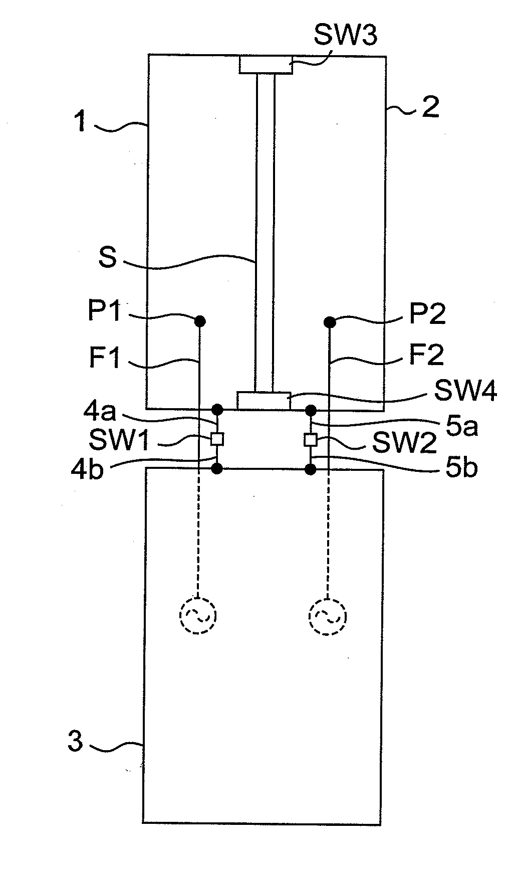
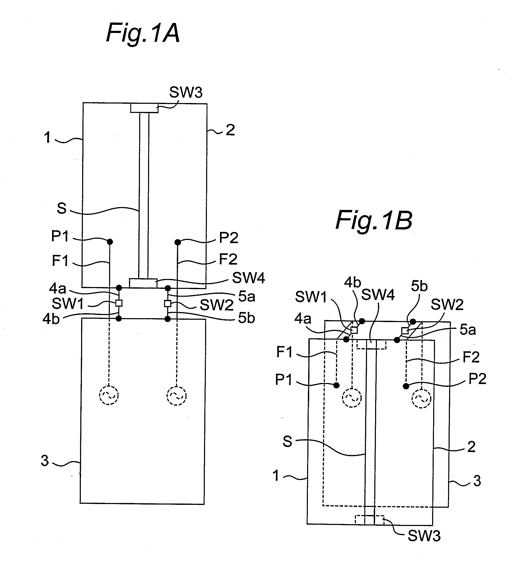
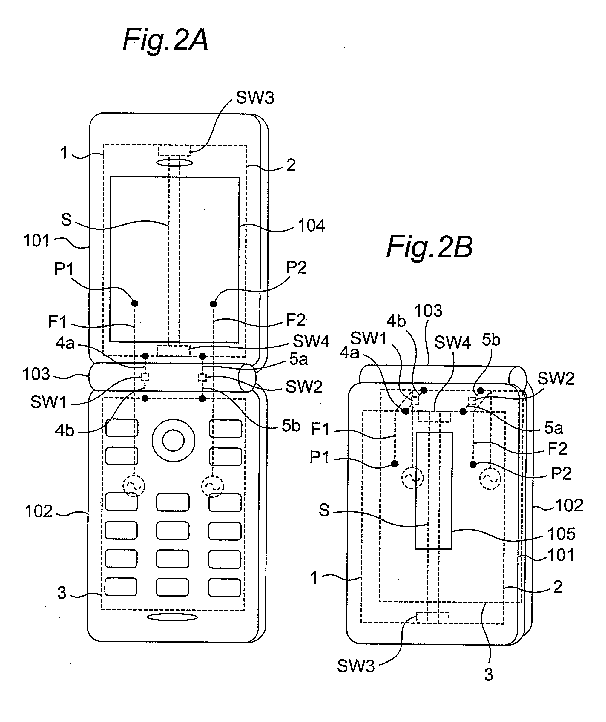
[0076]FIG. 1A is a schematic diagram showing an antenna apparatus in its open state, according to a first preferred embodiment of the present invention. FIG. 1B is a schematic diagram showing the antenna apparatus of FIG. 1A in its closed state. FIGS. 2A, 2B, 3A, and 3B are schematic diagrams showing an implementation of a mobile phone provided with the antenna apparatus of FIGS. 1A and 1B. FIGS. 4 and 5 are block diagrams showing a circuit configuration of the antenna apparatus of FIGS. 1A and 1B.

[0077]Referring to FIG. 1A, the antenna apparatus includes two antenna elements 1 and 2, each made of a conducting plate having at least one linear edge. The antenna elements 1 and 2 are opposed to each other at respective one edges thereof so as to be close to each other, thus resulting in a parasitic slit S formed between the antenna elements 1 and 2. As shown in FIGS. 2A and 2B, the parasitic slit S is provided in parallel to a longitudinal direction of a mobile phone (i.e., an up-down ...

second preferred embodiment

[0108]FIG. 20A is a schematic diagram showing an antenna apparatus in its open state, according to a second preferred embodiment of the present invention. FIG. 20B is a schematic diagram showing the antenna apparatus in FIG. 20A in its closed state. FIGS. 21A to 23B are schematic diagrams showing an implementation of a mobile phone provided with the antenna apparatus of FIGS. 20A and 20B. FIGS. 24 and 25 are block diagrams showing a circuit configuration of the antenna apparatus of FIGS. 20 and 20B. The antenna apparatus according to the present preferred embodiment is characterized by being opened and closed by rotation, in a manner similar to as that of the conventional mobile phone described with reference to FIG. 27, instead of being opened and closed in a two-fold similar to that of the antenna apparatus according to the first preferred embodiment.

[0109]Referring to FIG. 20A, antenna elements 1 and 2 made of conducting plates are provided in a first plane, and a ground conducto...


PUM


Abstract

When first and second housings are in an open state, first and second switches are electrically opened, and thus, a first antenna element and a ground conductor operate as a first dipole antenna, and a second antenna element and the ground conductor operate as a second dipole antenna with isolation from the first dipole antenna by the slit. When the first and second housings are in the closed state, the first and second switches are electrically closed, and thus, the first antenna element operates as a first inverted F antenna on the ground conductor, and the second antenna element operates as a second inverted F antenna on the ground conductor with isolation from the first inverted F antenna by the slit.

Description

BACKGROUND OF THE INVENTION[0001]1. Field of the Invention[0002]The present invention relates to a wireless communication apparatus such as a mobile phone with a housing which is made of two housing portions and which changes between open and closed states. More particularly, the present invention relates to an antenna apparatus for such a wireless communication apparatus.[0003]2. Description of the Related Art[0004]Some mobile phones are configured with a housing which is made of two housing portions and which changes between open and closed states, as shown in FIGS. 26A, 26B, 27A, and 27B. FIGS. 26A and 26B are diagrams respectively showing an open state and a closed state of a clamshell (two-fold) mobile phone according to a prior art. In this mobile phone, an upper housing 101 provided with a speaker, a display, etc. and a lower housing 102 provided with a microphone, a keyboard, etc. are coupled to each other through a hinge portion 103, and can be folded. Further, the upper ho...

Claims


Application Information

Patent Timeline
Patent Type & Authority Applications(United States)
IPC IPC(8): H01Q1/24H01Q1/00H01Q1/08H01Q1/52H01Q3/24H01Q9/28H01Q13/08H01Q21/28H04B1/38H04B1/40H04B7/04H04M1/00H04M1/725
CPCH01Q9/42H01Q1/243
Inventor SAKATA, TSUTOMUYAMAMOTO, ATSUSHIAMARI, SATORU
Owner PANASONIC INTELLECTUAL PROPERTY CORP OF AMERICA
Learn More